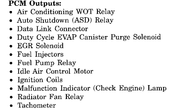
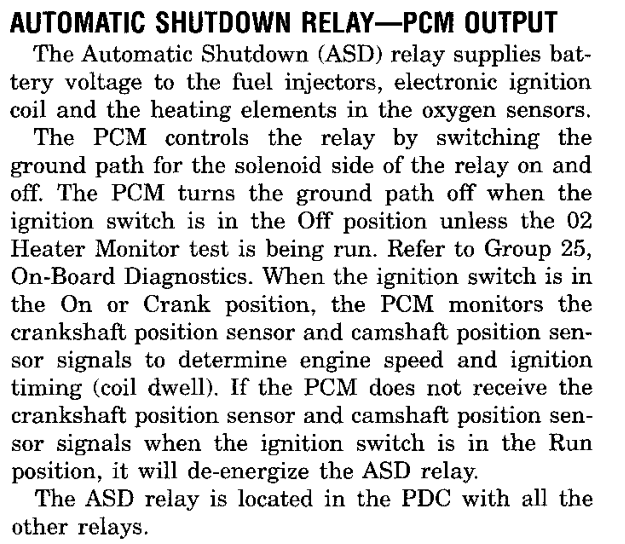
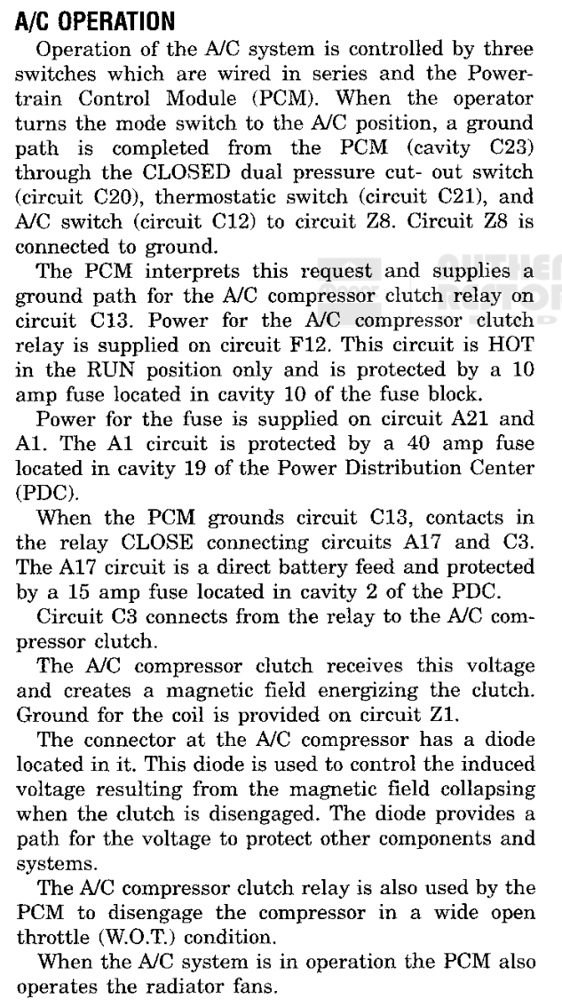
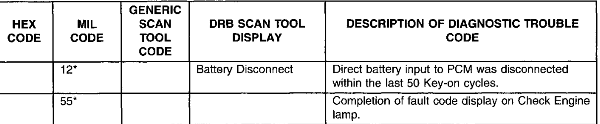
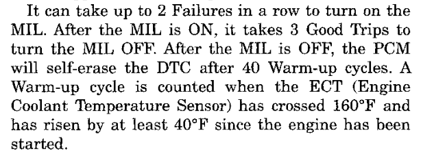
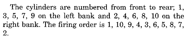
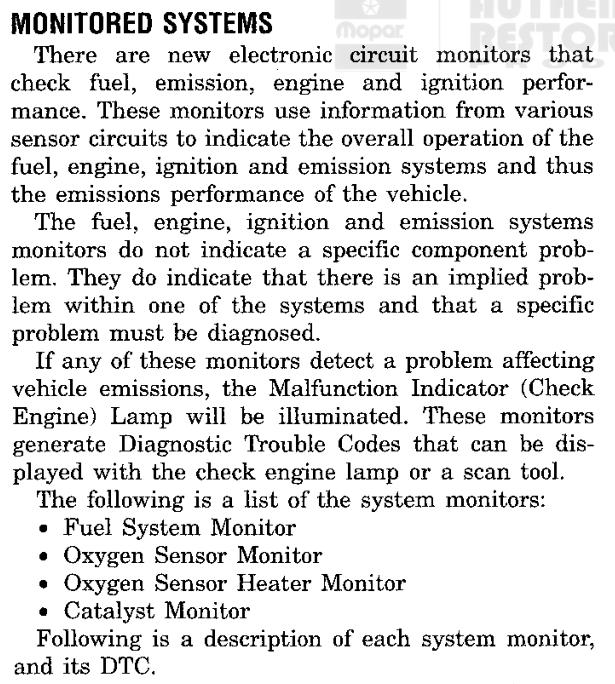
HOW TO USE THIS MANUAL. Each group follows the order of a factory service manual: Description and Operation, Diagnosis and Testing, Specifications. Calibration structures appear in the group that uses them and, complete, in Group 9. Routine addresses such as 018588 and ROM addresses such as 3D65 refer to the reference image; select one to open its entry.
SR0 · INTRODUCTION0 - 1
ABOUT THIS MANUAL
DESCRIPTION AND OPERATION
PURPOSE AND SCOPE
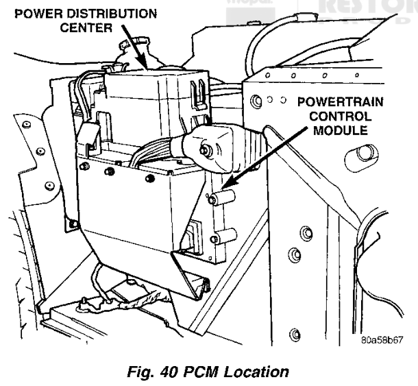
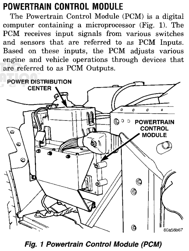
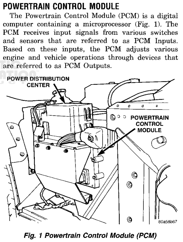
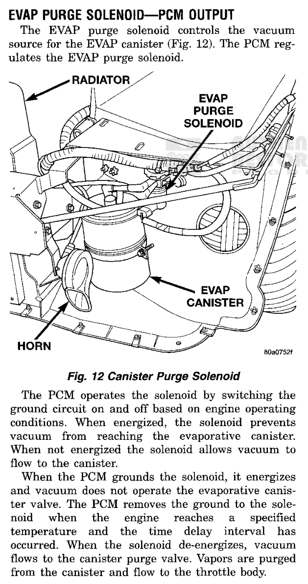
This manual describes the software of the 1997 Viper SR powertrain control module (PCM). It covers the 8.0L V10 engine and the JTEC controller. The PCM is a digital computer containing a microprocessor, mounted underhood next to the heater motor blower housing (Fig. 1). It reads its inputs, makes its control decisions, and operates its outputs as described in the service manual. This manual explains the program that makes those decisions.
Every statement in this manual is taken from one reference image, the 256 KiB flash image VIP_2A03.ori, with calibration 04848703AF. The image is identified in 0-2 Reference Image Identification. The processor is a Motorola 68HC16. The image occupies CPU addresses 000000 through 03FFFF. Where this manual describes vehicle wiring, connectors, or component operation, it follows the 1997 Dodge Viper Service Manual and identifies the service manual group.
The manual describes what the software does with its inputs, flags, requests, tables and output commands. It does not replace the service manual for vehicle-side diagnosis and repair.
Fig. 1 PCM Location (Group 14)
HOW THIS MANUAL IS ORGANIZED
The manual is divided into groups in the same way as the service manual. Group 0 introduces the manual, identifies the reference image, and defines terms (0-3 Glossary). Group 1 describes how the program starts, schedules its work and handles interrupts (1-2 Startup and Initialization, 1-3 Job Scheduling, 1-4 Interrupts). Groups 2 through 8 describe individual systems: engine events, fuel, ignition, outputs, speed and transmission, sensor fault handling, and on-board diagnostics.
Each system section is arranged in the service manual order:
PART
CONTENTS
Description and Operation
The routines, signals and calibration values that make up the function, with flowcharts and listings
Diagnosis and Testing
DRB output tests and trouble codes that use the function, where they exist
Specifications
Calibration values read from the reference image, and PCM connector circuits
A table of the calibration structures used by the section closes each system section. Group 9 holds the calibration data: the flash structure of the complete image (9-1 Flash Structure) and every calibration table, curve, setting and record, grouped by system. Group 10 is the reference group. It holds the PCM connector pinouts (10-1 PCM Connector Pinouts), the work schedule tables (10-2 Work Schedule Tables), the routine index (10-3 Routine Index) and the alphabetical index (10-4 Alphabetical Index).
ROUTINE, RAM AND ROM ADDRESSES
A routine is named by the six-digit hexadecimal address of its first instruction, for example the A/C clutch control routine 018588. Each routine address in the text is a link to its entry in the routine index, which gives the routine name and every section that refers to it. Section 5-2 Accessory and Evaporative Outputs describes this routine in full.
Working values are held in RAM at addresses F8000 and above. At reset, the initialization routine (020000) selects bank F and loads the Z index register with 8000 (Fig. 2). Instructions written as an offset from Z therefore address F8000 plus the offset: LDAA 0x5a,Z reads F805A. The manual always gives the full five-digit RAM address.
020000LDAB #0xf; bank F020002TBZK ; Z bank02000ALDZ #0x8000; Z = F8000
Fig. 2 RAM Base Selected at Reset
RAM from F8000 through F87FF is cleared at every reset. RAM from F8800 upward holds retained values. The reset routine preserves them when their stored check sum matches, and seeds default values when it does not (1-2 Startup and Initialization).
A single bit is written with its mask value in hexadecimal. "F8107, bit 20" is the bit tested and set by #0x20 in the byte at F8107.
Calibration values are read from ROM by their four-digit address, for example 3D65. In a listing a ROM operand is written without an index register: CMPA 0x3d65 compares the accumulator with the calibration byte at 3D65 (Fig. 3). Each calibration value printed in this manual is read from the reference image when the manual is built, and its raw value is shown when the pointer rests on it.
0186DALDAA 0x5a,Z; RAM F805A, engine speed0186F0CMPA 0x3d65; ROM 3D650186F6BSET 0x674,Z,#0x20; RAM F8674, bit 200186FCLDAA 0xa6,Z; RAM F80A6, coolant018712CMPA 0x3d67; ROM 3D67018718BSET 0x674,Z,#0x10; RAM F8674, bit 10
Fig. 3 RAM Signals and ROM Calibration in a Listing
FIGURES AND FLOWCHARTS
Figures are numbered within each section. Four kinds of figure are used:
Flowcharts show the order of decisions in a function. Shaded cards mark the request, flag or command that the function produces. A card that carries a routine address links to that routine.
Listings reproduce the decisive instructions of a routine from the reference image, with the instruction address at the left and a comment at the right. Readable C listings show the same logic in C. Each one is checked against the original instructions.
Calibration figures draw a table as a heat map or a curve, with its ROM address and the routine that reads it. Each one links to its complete entry in Group 9.
Service manual figures are reproduced from the 1997 Dodge Viper Service Manual. The caption gives the service manual group.
The three kinds of reference meet in each system section (Fig. 4). A routine reads RAM signals and ROM calibration and produces a request. An output command carries the request to a PCM circuit, and the service manual figure shows that circuit in the vehicle.
Fig. 4 How References Relate
REVISIONS
This manual is revised as more of the PCM software is documented in readable C. Sections gain listings, flowcharts and calibration figures with each revision. Every revision is built from the same reference image. The build checks the image, every routine address, every listing address and every printed calibration value, so a page that disagrees with the image is not published.
SPECIFICATIONS
CONVERSIONS
The PCM stores values as raw counts. The manual prints them in physical units with the conversions below. A value with no conversion is printed in hexadecimal.
QUANTITY
STORED AS
CONVERSION
EXAMPLE
Engine speed, word
F805A word
word ÷ 8 = rpm
—
Engine speed, byte
F805A high byte, ROM limits
count × 32 = rpm
ROM 3D65 = 5632 rpm
Coolant temperature
F80A6, ROM limits
count − 64 = °C
ROM 3D67 = 121 °C
Unconverted byte
ROM
hexadecimal
ROM 3DE3 = DA
Timer reload or count
ROM word
decimal counts
ROM 3D5B = 91 counts
ADDRESS RANGES
RANGE
CONTENTS
REFER TO
000000–03FFFF
Flash image: program, calibration and diagnostic data
ROM 002814–002836 · 35 bytes · Read by 0109DC, 011B14
Fig. 5 Engine Speed Axis — breakpoints convert at 32 rpm per count — complete entry 9-7, Fig. 4
0 - 20 · INTRODUCTIONSR
REFERENCE IMAGE IDENTIFICATION
DESCRIPTION AND OPERATION
REFERENCE IMAGE
This manual describes one PCM program: the reference image VIP_2A03, a 262,144-byte (256 KiB) copy of the main processor flash memory. Every routine address, table address and calibration value in this manual is an offset into that image. The build of this manual checks the SHA-256 hash of the image before it reads any value, so every figure and specification is taken from the same bytes. Refer to Specifications.
The PCM is a digital computer containing a microprocessor (Fig. 1). In this image the main processor is a Motorola CPU16-family (68HC16) device. The program uses the CPU16 20-bit address space: the bank registers extend 16-bit addresses, program code runs in banks 0 through 2, and RAM and the on-chip modules sit in bank F. The serial communications interface (SCI) status and data registers, for example, are read and written at FFC0C and FFC0E.
Fig. 1 Powertrain Control Module (Group 14)
CALIBRATION IDENTIFICATION
The image carries calibration number 04848703AF. The long word at 000200 points to the identifier at 002738. The identifier is seven bytes: four bytes of packed BCD (04848703), the ASCII revision letters 41 and 46 ("AF") and a final byte A0. A second copy of the same seven bytes begins at 00273F (Fig. 3).
Chrysler's scan-tool flash catalog lists 04848703AF for the 1997 SR 8.0L BUX application (Built Up Export, the export Viper). It supersedes calibrations 04848703AA, AB, AC, AD and AE and is released under TSB 18-24-98. The domestic 1997 application carries a different calibration number (04848702).
The PCM reports its identification through the SCI diagnostic service (00C800). Request 2A selects the identification lookup at 00DF22. The request carries a one-based index from 1 to 31 (01–1F). The bound test is a signed compare, so indexes 81 to FF are also answered: they read address words beyond the end of the list and return other bytes of the image. Index 00 and indexes 20 to 80 send nothing. The routine selects one of two address lists by the state byte F835A, which startup reads from logical EEPROM location 1EF: the list at F741 when the byte holds 55, otherwise the list at F703. It loads the indexed address, reads that byte of the image and sends it with the SCI transmit routine (00EBC0), which waits for the transmitter-empty flag before it writes the data register (Fig. 2). The leading entries of the F703 list address the first identifier copy; those of the F741 list address the second. Both lists also address calibration bytes 3F1E–3F2E and the bytes 2746–274B (8-7 Scan Tool Commands).
The image holds engine profiles for several engine configurations. The calibration selects one of them at startup. The reset initialization routine (020000) reads the engine profile selector at 002707 and compares it with eight single-bit values. In this image the selector is 02, and the branch at 0204CA selects the V10 profile at 0006CA and the output-mask table at 0008BA (Fig. 5). The routine stores both pointers in RAM (F8058 and F8177). Engine routines read the profile through the stored pointer from then on, so no other profile takes part in operation. Refer to 1-2 Startup and Initialization.
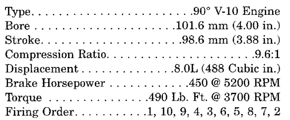
The selected profile records a cylinder count of 10 at 0006CB and again at 000702. The firing-order sequence at 0006E4 lists cylinders zero-based. Adding one to each entry gives 1-10-9-4-3-6-5-8-7-2, the firing order of the 8.0L V10 engine (Fig. 6). Two more copies follow at 0006EE and 0006F8, each rotated one position further. The cylinder-indexed accumulator routine (0119EE) reads the copy at 0006F8 through the profile pointer, selected by profile byte 0006D3 (02), and the engine event interrupt (028F24) uses the cylinder count to form its cylinder-position index. The output-mask table holds ten distinct single-bit masks. The fuel pulse-width routine (0109DC) and the startup fuel routine (011B14) read it through the stored mask pointer. Refer to 2-1 Engine Position and Timing.
The image begins with the CPU16 reset vector. Its four words set the initial bank registers, program counter, stack pointer and IZ register. The program counter word 0000 with program bank 1 starts execution at 010000, the first entry of a 27-entry jump table, which jumps to the reset initialization routine at 020000. The 252 interrupt vector words from 000008 to 0001FF follow. All but one point to short jump stubs in bank 0; vectors without a handler point to the default fault stub 00081E, which jumps to the default trap entry 02194A. The SCI vector (4E, at 00009C) points directly to the SCI transmit interrupt routine (00EC5A). The vector table is drawn in 1-4, Fig. 2; refer to 1-4 Interrupts.
Calibration and configuration data occupy the low 64 KiB, separated by FF fill. The principal calibration area runs from 002600 to 003F9F and holds the engine selector and the identifier. The SCI diagnostic service and its protocol tables sit between 00C800 and 00FC01. The main program begins at 010000 and ends at 02A00F; a copyright record follows, and FF fill runs from 02A02A to the end of the image. The table below lists the principal regions. Refer to 9-1 Flash Structure for the block-by-block map.
ADDRESS RANGE
CONTENT
000000–000007
Reset vector: initial ZK/SK/PK, PC, SP and IZ
000008–0001FF
Interrupt vectors (252 words)
000200–000203
Calibration identifier pointer (to 002738)
000402–000855
Interrupt and fault jump stubs, with sensor conversion, schedule and engine-profile data between them
000934–000D33
Logical EEPROM address mapping
001000–0014F2
Configuration and diagnostic code records
002600–003F9F
Principal calibration area: engine selector, identifier, fuel and spark tables
The calibration number is four bytes of packed BCD followed by two ASCII letters. Application and bulletin are from Chrysler's scan-tool flash catalog.
CIRCUIT
PCM CAVITY
FUNCTION
D21
C1-27
SCI transmit (PCM perspective)
D20
C1-29
SCI receive (PCM perspective)
SR0 · INTRODUCTION0 - 3
GLOSSARY
TERMS
Active fallback flag
Working state that helps select a substitute input now. It can clear while a trouble code remains stored.
Calibration / map
Saved numbers or tables used to make control decisions, such as a starting fuel amount.
Cylinder bank
One group of cylinders on one side of a V-shaped engine.
Cylinder bank
One of the engine’s two cylinder groups. Bank-specific codes distinguish the group being monitored.
ECU / PCM
The engine computer. PCM is Chrysler's name for the powertrain control module.
Evaporative purge
Control associated with moving stored fuel vapors into the engine.
Fault trap
A path for an unexpected processor condition. These handlers do not return to the normal work in this image.
Flag
A small saved yes/no state, such as whether a calculation is requested.
Fuel trim
A fuel correction made using feedback. Short-term correction reacts to recent readings; long-term correction remembers an adjustment over time.
Fuel-inhibit mask
A set of selection bits that can tell the fuel calculation to hold back a prepared pulse for particular logical cylinders. Why each bit is set still needs tracing.
Held reading
A previous working value kept while the current sample is rejected. It can be stale.
Immediate-invalid flag
A software note that a local input check rejected a sample. The complete fault-code policy is a separate process.
Input capture
Hardware that remembers the timer value when an electrical edge arrives, so software can measure when it happened.
Internal fault id
An index used inside the program to select a diagnostic record. It is different from the reported OBD number and the legacy blink-code byte.
Interrupt
A signal that asks the processor to pause what it is doing and handle an event.
Interrupt service routine (ISR)
A small entry path that responds when the processor is interrupted. It may do work itself or ask the scheduler to do more.
Monitor qualification
Conditions and remembered observations that determine whether a diagnostic check may run and whether a result should be recorded.
P-number / trouble code
A diagnostic reporting code such as P0171. P means powertrain. The code identifies a condition the controller can report; it does not by itself identify a failed part.
Qualifying observation
A check result accepted after the relevant gates. It is not automatically a fixed amount of time or one driving trip.
Rich and lean
Rich means too much fuel relative to air. Lean means too little fuel relative to air.
ROM / flash image
A saved copy of program and calibration memory. It is not a recording of a running car.
Scheduler
The part of the program that chooses which ready job gets a turn.
SCI
A serial communication link used for diagnostic requests and responses.
Software-tracked position
A position the program remembers from its own requests. Without a traced feedback sensor, it is not proof of the actual mechanical position.
Stale reading
A saved value that has not received a fresh sample within the program’s allowed count. Its fallback value need not describe what the car is actually doing.
Substituted reading
A replacement value chosen from another signal, a stored value or an estimate. It is not a fresh measurement of the failed input.
Tick
One count of the scheduler's timebase.
Watchdog
A check that notices when expected activity has not happened. This program has checks for engine events and a separate processor watchdog.
Watchdog countdown
A value refreshed by expected activity and checked later. If the activity stops, an expiry path can change the software state. Here its unit is a check visit, not a confirmed number of seconds.
SR1 · SYSTEM OVERVIEW1 - 1
SYSTEM OVERVIEW
DESCRIPTION AND OPERATION
PCM SOFTWARE STRUCTURE
The Powertrain Control Module (PCM) is a digital computer containing a microprocessor. It receives input signals from switches and sensors and adjusts engine and vehicle operation through its outputs (Fig. 2). This manual describes the software in the PCM main processor of the 1997 Viper SR 8.0L V10, calibration 04848703AF.
The software does not run a single repeating list of engine calculations. After reset it initializes the hardware and settles in a one-instruction idle branch. All recurring work begins in interrupts. A periodic interrupt collects sensor readings and counts scheduler ticks; an engine-event interrupt records engine-position timing and flags each event. The periodic interrupt then carries the work through one chain of services: engine-speed calculation, engine-control dispatch (fuel and spark), serial and vehicle-speed service, and finally the job scheduler that runs the periodic jobs (Fig. 1).
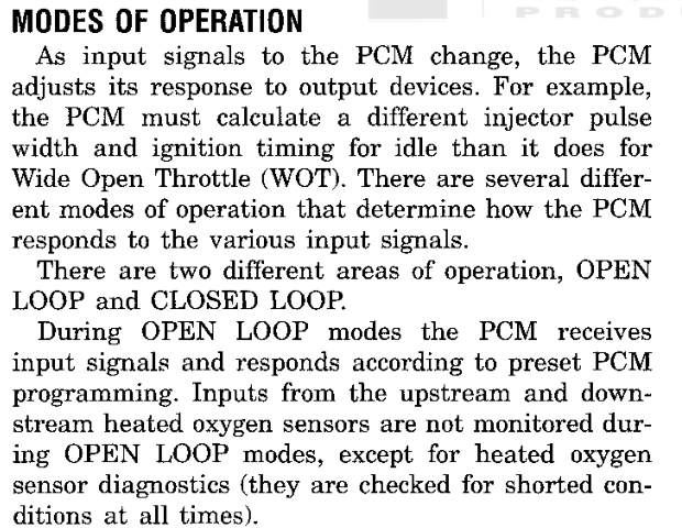
The PCM selects its responses from preset programming and its current operating state, which the service manual calls the modes of operation (Fig. 3). In the software, those modes are flags and phase states that the engine-speed service and the scheduled jobs set, and that the fuel, spark and output routines read.
Fig. 1 Main Software PathsFig. 2 Powertrain Control Module (Group 14)
The manual follows the same order as the software. Each group below covers one stage of the paths in Fig. 1.
The reset routine (020000) sets the bank registers, the stack and the common RAM base, then configures the chip selects, RAM mapping, analog converter, timer and serial modules. It loads the three periodic-group countdowns from the descriptors listed at ROM 0464 and reads the engine profile selector at ROM 2707. The value 02 selects the V10 engine profile at ROM 06CA and the ten fuel-output masks at ROM 08BA. Startup also queues the initial commands for the output hardware. Refer to 1-2 Startup and Initialization.
The reset routine lowers the interrupt mask at 0206AA, so interrupts are serviced during the remainder of startup. Near its end it writes 55 and then AA to the watchdog service register. Its final instruction jumps to the foreground idle branch (028500), a single branch to itself. The idle branch does not service the watchdog; the first job of the fastest periodic group (01FC58) does.
INTERRUPT-DRIVEN WORK
The periodic interrupt (028502) stores the analog converter results, services timer capture and overflow, updates vehicle-speed state and restarts conversion. Different sensor channels are processed on different visits. The interrupt then accounts for one scheduler tick (1-3, Fig. 1, 1-3 Job Scheduling). When engine-event maintenance is already running, the tick is added to the accumulated count F8006 and the interrupt returns. When the scheduler is active, the tick is accumulated for the scheduler to consume. Otherwise the countdown service (028906) decrements each group countdown directly and marks expired groups ready.
The engine-event interrupt (028F24) captures the event timestamps, updates synchronization history and profile state, reloads the engine-event watchdogs and sets work-pending flags. At and above the calibrated engine speed at ROM 2138, and with F80BC bit 40 set, it also sends the prepared fuel value of the bank selected by F80BC bit 20 (F82B0 or F82B2) directly to the output hardware. Refer to 2-1 Engine Position and Timing.
When the engine-event interrupt has captured an event, the periodic interrupt calls the engine-speed service (026CFC). It consumes the timestamp history, calculates engine speed F805A, updates the startup and running phase flags, and sets engine-control pending bits in F80D2. The dispatcher (028992) takes the lowest set bit, clears it, and calls the handler listed for it at ROM 0478 (1-3, Fig. 3, 1-3, Fig. 4). It repeats until no pending bit remains. The phase flags decide whether the startup or the running fuel and spark routines are requested.
When the pending bits are clear, the speed and serial service (01E14E) services the output queue, vehicle speed and the SCI link. When the SCI receiver holds data, the service calls the diagnostic service (00C800). Refer to 6-1 Vehicle Speed Input and 8-1 Diagnostic Overview. The service then enters the job scheduler, unless the scheduler is already running (Fig. 4).
Two further interrupts operate alongside these paths. A level-5 interrupt (029F90) acknowledges its source and services the output queue. The SCI transmit interrupt (00EC5A) sends serial data from a table. The interrupt vectors are listed in 1-4, Fig. 2; refer to 1-4 Interrupts.
PERIODIC JOB SCHEDULING
Periodic jobs are organized in three groups, each a list of three-byte records: a job routine and its priority state. The scheduler (028B6A) scans the three group states and selects the ready group with the greatest priority. It runs one record of that group (028BB4), advances the group cursor, and scans again, so jobs of different groups interleave while each group keeps its listed order (1-3, Fig. 8). A record of FFFF ends a group. Ticks that arrive while a job runs are applied to the countdowns (028C4A) before the next scan. When no group is ready, the scheduler clears its active flag and returns from the interrupt.
A group that comes due while its previous release is still running is marked with state bit 80; it is not released twice. Within a group, many jobs run their full body only under their own conditions or subrates. Refer to 1-3 Job Scheduling, 1-5 Scheduled Jobs and 1-6 Supporting Jobs.
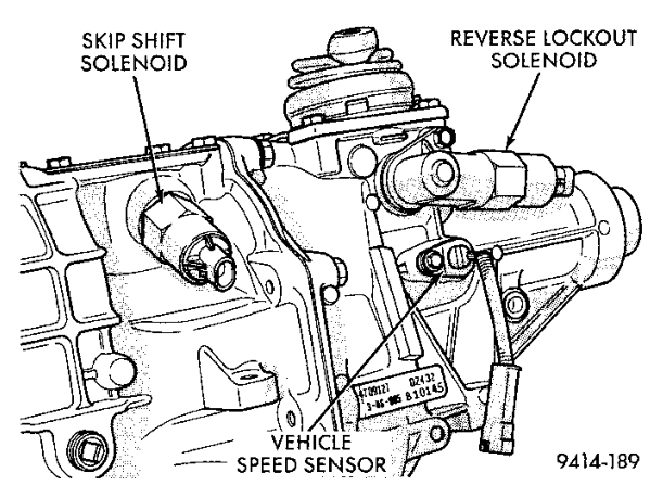
The fastest group carries the watchdog service, transmission dispatch and reverse lockout (6-2 Transmission Controls, 6-3 Reverse Lockout), coolant and intake-air filtering, deceleration and engine-speed cut requests, the changed discrete-output commands (029AFC), the engine-event watchdog expiry (013E3E), OBD requests, and the purge and oxygen-feedback jobs (5-2 Accessory and Evaporative Outputs, 3-2 Fuel Feedback). The slower groups carry fuel timers, transmission temperature, event-loss output state and fuel-cut profile countdowns.
OUTPUT HANDOFF AND FAULT RECORDS
The software sends its results to the output hardware as commands. The command queue (029270) holds them and the QSPI service (0293F6) transmits them. The running fuel routine stores bank results F82B0 and F82B2; the spark routine stores its final timing in F83D9 and queues spark command 24. Discrete requests in F8106 through F8108 are queued only when they change. Refer to 5-1 Output Commands.
CPU exceptions use a separate path. The exception entries (0218C0 onward) record an internal fault byte at F8A06 and enter a port-write loop (021954). These internal codes are not diagnostic trouble codes.
SPECIFICATIONS
DESCRIPTION
SPECIFICATION
ROM
Engine profile selector (V10)
02
2707
Periodic groups
3
040E
Group 1 period
22 ticks
08DC
Group 2 period
172 ticks
08ED
Group 3 period
1953 ticks
090A
Engine-control handler table
8 slots
0478
Group periods count periodic-interrupt ticks. Group 1 holds 4 jobs, group 2 holds 8 and group 3 holds 12.
Every reset of the PCM main processor enters the reset routine (020000). The routine runs once, from top to bottom, and prepares the processor, memory, engine profile and companion devices before any engine control work is allowed to run (Fig. 2).
The first instructions set the stack and Z bank registers to F and the remaining bank registers to 0, place the stack at F8FFC and set the common data base to F8000. The routine then programs the system integration module: clock synthesizer, system protection, chip selects and port E. It services the software watchdog with the 55, AA sequence as part of this setup (Fig. 1). The analog converter, general-purpose timer and queued serial module are configured next, and the queued serial transfer memory is cleared.
020000LDAB #0xf020002TBZK ; Z bank = F020004TBSK 020006LDS #0x8ffc; stack F8FFC02000ALDZ #0x8000; base F800002000ELDAB #0x0020010TBEK 020012TBXK 020014TBYK 020016LDAA #0x7f020018STAA 0x7a04,Z; clock synthesizer02001CLDAA #0xb402001ESTAA 0x7a21,Z; system protection020022LDAA #0x55020024STAA 0x7a27,Z; watchdog 55020028LDAA #0xaa02002ASTAA 0x7a27,Z; watchdog AA
Fig. 1 Bank Registers, Stack, Base and WatchdogFig. 2 Startup Sequence
RETAINED MEMORY CHECK
Working memory is divided into two areas. The area from F8000 to F87FF holds the running state of every control routine. The area from F8800 to F8A04 holds retained state, including the active and stored fault flags and the blink-code arming count. A check word at F8800 protects the retained area.
Startup calls the retained-sum routine (013D08), which adds the 515 bytes from F8802 to F8A04 into a 16-bit sum, and compares the result with the check word (Fig. 3).
Sum matches. The retained area is kept, including the blink-code arming count at F89A6. Startup overwrites the check word and continues.
Sum does not match. Startup clears F8800 through F8A05 and seeds the retained area with default values read from calibration. The active fault flags at F8808 and the arming count are cleared.
Both paths then clear the working area F8000 to F87FF, so the working area starts from zero on every reset. Later in startup the reset routine also clears the active fault flags of selected checks (7-2 Sensor Recovery). The power-input service (013A66) stores a fresh sum in F8800 when it saves retained state. Blink-code arming and its use of the retained count are described in 8-4 Entering Blink Code Mode.
0201ECJSR 0x013d08; sum F8802–F8A040201F0CPD 0x800,Z; check word F88000201F4BNE 0x0202060201F6LDD 0x805,Z0201FATBA 0201FCCOMB 0201FESTD 0x800,Z020202LBRA 0x020392; keep retained area020206CLRW 0x800,Z; clear retained area02020ACLRD 02020CLDE #0x800020210STD E,IZ020212ADDE #0x2020214CPE #0xa05; through F8A05020218BCS 0x020210020392LDE #0x0; working area020396CLRD 020398STD E,IZ02039AADDE #0x202039CCPE #0x800; through F87FF0203A0BCS 0x020398
Fig. 3 Retained Sum Compare and Memory Clear
ENGINE PROFILE SELECTION
The program image serves several engine configurations. A single selector byte at ROM 2707 chooses which one runs. Eight selector values each name a profile record, a mask table and a two-byte configuration pair; a selector outside the eight takes a default profile (Fig. 4).
The Viper selector is 02. It selects the ten-cylinder profile at ROM 06CA and the mask table at ROM 08BA. Startup stores the profile pointer at F8058 and the mask-table pointer at F8177, where the engine-event and fuel routines read them. The configuration pair from ROM 2134 is stored at F8012 and F8013.
The profile carries the firing sequence at ROM 06E4 as ten zero-based cylinder numbers. Adding one to each entry gives 1-10-9-4-3-6-5-8-7-2, the firing order of the 8.0L V10 engine (Fig. 5). Refer to Specifications. The contents of the profile and the routines that read it are described in 0-2 Reference Image Identification.
With the profile in place, startup sets the startup-fuel phase flag (F80D1 bit 80) and the spark-initialization phase flag (F80D1 bit 20). The first engine events therefore schedule the startup fuel calculation and spark initialization instead of the running calculations. Startup also loads the engine-event watchdog count at F80C7 from ROM 2104. Phase changes after the first events are described in 2-1 Engine Position and Timing.
COMPANION PROCESSOR CHECK
The PCM main processor exchanges commands with a companion processor over the queued serial peripheral interface. Before it sends any configuration, startup waits for the timer pulse accumulator to count, then performs a two-transfer check (Fig. 7).
The first transfer sends the first byte of the selected profile, 09. The reply is stored at F816E and F8511. The second transfer sends zero. The second reply, added to the profile byte, must equal zero. Any other reply sends the processor back to the reset entry, and the complete startup sequence runs again. After a correct reply the two-transfer check runs a second time, with the same restart on a wrong reply.
020510LDAA 0x790d,Z; wait for pulse count020516LDX 0x58,Z02051ALDAB 0x0,X; profile byte02051ESTD 0x7d20,Z; first transfer02052ELDE #0x8404020532STE 0x7c1a,Z020536LDAA 0x7c1f,Z; wait for completion020542LDAA 0x7d01,Z; first reply020546STAA 0x16e,Z020556CLRW 0x7d20,Z; second transfer: zero02055ASTE 0x7c1a,Z02055ELDAA 0x7c1f,Z020576LDAB 0x7d01,Z; second reply02057ALDAA 0x0,X02057CABA ; reply + profile byte02057ELBNE 0x020000; nonzero: restart
Fig. 7 Profile Byte Exchange and Restart on Mismatch
INITIAL COMMANDS AND SENSOR READINGS
Directly after the working-area clear, before profile selection, startup loads the three periodic work-group countdowns at F8000, F8002 and F8004 from the group descriptors listed at ROM 0464. It then runs a calibrated delay of 16000 loop counts.
The routine sends its initial configuration and output states to the companion processor through the command queue (029270) and drains the queue with the serial queue service (0293F6). The routine contains fifty command requests. Partway through, at 0206AA, startup relaxes the interrupt priority mask and waits until the queue holds four entries or fewer. From this point interrupt service runs alongside the rest of startup. Interrupt routing is described in 1-4 Interrupts.
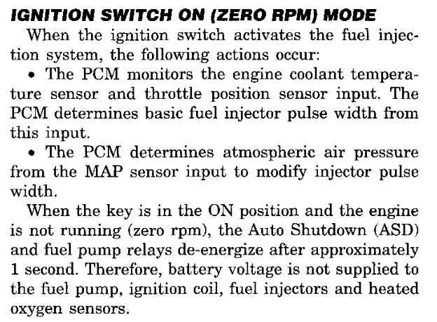
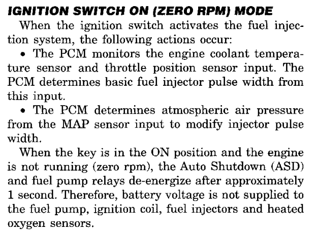
Startup takes the first sensor readings with the same routines the running software uses. Temperature readings are converted through the thermistor curve at ROM 0410. The coolant reading passes through the coolant range check (019C06). A rejected reading is not used at once: startup starts a fresh conversion and checks the new result (Fig. 8). When the second reading is also rejected, startup checks the intake air reading (019CDC) and takes the coolant substitute value (01F99A). The accepted or substituted coolant value is stored as both the working value F80A6 and the start value F80A7. The MAP reading is converted with its fallback routine (029A56), and the coolant-dependent transient fuel parameters are set (013954). The service manual describes the PCM's key-on, zero-rpm inputs in Ignition Switch On (Zero RPM) mode (Fig. 9).
FIRST COOLANT READING · 020000range check and retry
020D92JSR 0x010070; range check020D96BRCLR 0x11f,Z,#0x10,0x020dce; accepted020D9CLDE #0x30; start conversion020DA0STE 0x770c,Z020DA4LDAA 0x770e,Z; wait for completion020DA8BPL 0x020da4020DAALDD 0x7712,Z; new reading020DAESTD 0x34,Z020DB2JSR 0x010070; check again020DB6BRCLR 0x11f,Z,#0x10,0x020dce020DBCJSR 0x010074; intake air check020DC0JSR 0x01f99a; coolant substitute020DC4LDAB 0xa6,Z020DC8STAB 0xa7,Z020DCCBRA 0x020de2020DCELDX #0x410020DD2LDE 0x34,Z020DD6JSR 0x010050; thermistor curve020DDASTAB 0xa6,Z; working value020DDESTAB 0xa7,Z; start value
Fig. 8 Coolant Range Check with One Fresh ConversionFig. 9 Ignition Switch On (Zero RPM) Mode (Group 14)
HANDOFF TO INTERRUPT OPERATION
The last block of startup services the watchdog with 55, AA, writes the general-purpose timer control word and clears the interrupt priority mask (Fig. 10). The routine then jumps through the bank-1 entry at 01001C to the idle branch at 028500. That instruction branches to itself.
The idle branch carries no control work. Engine events, the periodic timer and the serial interfaces enter through interrupts, and the job scheduler runs the periodic work groups from the interrupt frame (1-3 Job Scheduling). The idle branch does not service the watchdog; the first scheduled job wrapper (01FC58) does (1-5 Scheduled Jobs).
Fig. 10 Final Watchdog Service, Interrupt Mask and Jump to Idle
DIAGNOSIS AND TESTING
PROCESSOR EXCEPTION STOPS
Processor exceptions and unexpected interrupt levels do not return to normal operation. Each exception vector leads to a short entry that stores an exception code at F8A06, just above the retained area, and enters the port latch loop (021954). The loop repeatedly writes port C with bits 08 and 80 cleared and does not service the watchdog. The entries and their codes are listed in 1-4 Interrupts. These codes are internal processor records; they are separate from the diagnostic trouble codes described in 8-2 Fault Reporting.
REPEATED STARTUP
A wrong second reply in the companion processor check returns the main processor to the reset entry before any configuration commands are sent. Each repeat clears working memory and repeats the retained-sum check, profile selection and companion check in full.
SPECIFICATIONS
DESCRIPTION
SPECIFICATION
ROM
Engine profile selector
02
2707
Companion check byte (first profile byte)
09
06CA
Configuration pair
5D4E
2134
Engine-event watchdog preload
5B
2104
Startup delay loop
16000 counts
2108
Work group 1 period
22 ticks
08DC
Work group 2 period
172 ticks
08ED
Work group 3 period
1953 ticks
090A
FIRING POSITION
PROFILE ENTRY
CYLINDER
1
0
1
2
9
10
3
8
9
4
3
4
5
2
3
6
5
6
7
4
5
8
7
8
9
6
7
10
1
2
Profile entries are zero-based cylinder numbers stored from ROM 06E4. Work group periods are scheduler ticks.
CIRCUIT
PCM CAVITY
FUNCTION
F12
C3-2
Fused ignition RUN/START supply
A14
C3-22
Fused battery supply
Z12
C3-31
Ground
Z12
C3-32
Ground
SR1 · SYSTEM OVERVIEW1 - 3
JOB SCHEDULING
DESCRIPTION AND OPERATION
INTERRUPT-DRIVEN WORK
The PCM software has no foreground loop that calls fuel, spark and diagnostic routines in turn. Startup (020000) ends at an idle branch (028500) that jumps to itself. All recurring work enters from interrupts (1-4 Interrupts).
Two kinds of work are kept. Pending engine work is a set of eight request bits at F80D2 that engine events set; each bit selects one entry of the pending-work table. Periodic work is three groups of jobs, each released by its own countdown of scheduler ticks. Pending engine work always runs ahead of periodic work, and a periodic job can be interrupted to serve it.
The periodic interrupt (028502) supplies the tick. After it samples the converters and services timer capture, its tail decides how the tick is used (Fig. 1):
When engine work is in progress (F80D1, bit 04), the tick is added to the elapsed-tick count F8006 and the interrupt returns at once.
When a periodic job is running (F80CE, bit 02), the tick is added to F8006 (02896A). The scheduler applies it after the current job.
Otherwise the tick is applied directly: each group countdown decreases by one (028906).
Both of the last two paths then set the engine-work flag. When a captured engine event is waiting (F80CE, bit 04), the engine-speed routine (026CFC) runs with the interrupt mask raised and sets the pending bits for that event (2-1 Engine Position and Timing). The pending bits are then served, followed by the shared speed and serial service (01E14E), which clears the engine-work flag. If a periodic job was interrupted, the interrupt returns into that job. If not, the routine sets the scheduler-active flag, lowers the interrupt mask and enters the scheduler.
Fig. 1 Periodic Interrupt Tail
PENDING ENGINE WORK
The engine-speed routine reads a flag byte for each engine event from the engine profile (Fig. 2). One flag requests the engine-interval history job (bit 04). Another requests spark timing: bit 10 selects spark initialization while the spark-initialization phase flag F80D1 bit 20 is set, and bit 02 selects ordinary spark timing otherwise. A third requests fuel: bit 08 selects startup fuel while the startup-fuel phase flag F80D1 bit 80 is set, and bit 01 selects running fuel otherwise. The fuel and spark jobs are described in 3-1 Fuel Amount and 4-1 Spark Timing.
The pending-work dispatcher (028992) serves the bits in order from bit 01 upward (Fig. 3). It clears the selected bit before it calls the job. The job address comes from the pending-work table at ROM 0478 (Fig. 4). After each job, when the QSPI command queue holds work (F80CD not zero), the queue service (0293F6) runs before the next bit is chosen. The dispatcher repeats until F80D2 is zero. Bits 20, 40 and 80 point to entries that return at once.
The number of periodic groups is stored at ROM 040E (3). ROM 0464 holds a pointer to each group descriptor. A descriptor begins with the group's reload count in ticks, followed by three-byte job records: a two-byte job address and a state byte. A word of FFFF ends the group (Fig. 8). The complete group listings are in 10-2 Work Schedule Tables.
Each group keeps three values in RAM: a countdown (F8000, F8002, F8004), a record cursor (F8014, F8016, F8018) and a state byte (F8028, F8029, F802A). Startup loads each countdown from its descriptor (1-2 Startup and Initialization).
When a countdown reaches zero, it is reloaded with the group period (Fig. 5). An idle group (state zero) becomes ready: its cursor is set to the first record and its state to that record's state byte. A group that is still working through its records is not restarted; its state receives bit 80 instead, which marks the pass as overrun. A release that occurs during an overrun pass adds no further mark.
028928DECW 0x0,Z; countdown − 102892CBNE 0x02895202892EPSHM IX,IY028930AEY 028932LDY 0x0,Y028934LDD 0x0,Y; reload count028936STD 0x0,Z028938LDAB 0x0,X; group state02893ABEQ 0x02894202893CORAB #0x80; overrun mark02893ESTAB 0x0,X028940BRA 0x028950028942AIY #0x2; first record028944LDAA 0x2,Y; first state byte028946STAA 0x0,X028948LDX #0x801402894CAEX 02894ESTY 0x0,X; record cursor028950PULM IY,IX028952AIZ #-0x2028956AIX #-0x102895ASUBE #0x2; next group02895EBPL 0x028928
Fig. 5 Group Countdown and Release
JOB SELECTION AND EXECUTION
The scheduler selects the group whose state byte has the greatest low-order digit (028B6A, Fig. 6). The state byte of a group's current record is therefore its priority. All records carry state 08 except the fourth record of group 1, which carries 07. Within a pass the scan begins at the group selected last, and a later group of equal value replaces the earlier choice, so groups of equal priority take turns. When no group is ready, the scheduler clears the scheduler-active flag and returns from the interrupt to the idle branch or to the interrupted code.
The record service (028BB4) calls one job, then advances the cursor by one record (Fig. 7). The group state is updated as follows:
Next record present, no overrun mark: the state becomes that record's state byte.
Next record present, overrun mark set: when the next state byte is lower than the first record's, the group restarts at its first record; otherwise the group continues and keeps the mark.
End of group, no overrun mark: the state is cleared and the group is idle.
End of group, overrun mark set: the group restarts at its first record.
In group 1, an overrun pass therefore returns to the first record without running the fourth job.
After each job the scheduler checks F8006. When ticks have accumulated, the update service (028C4A) subtracts them from all three countdowns. A countdown that reaches or passes zero is released as described above; when the overshoot is smaller than the period, the remainder is carried into the new count. The consumed ticks are then subtracted from F8006 with the interrupt mask raised, so ticks that arrive during this update are kept. The scheduler then selects again.
028B6ACLRD 028B6CPSHM D028B6ETSY 028B70LDAB #0xf028B72TBXK 028B74LDX #0x8028; group states F8028028B78LDE 0x0,Y; start at last group028B7CCLRD 028B7EPSHB 028B80LDAB E,IX028B82ANDB #0xf; priority digit028B84STAB 0x139,Z028B88PULB 028B8ACMPA 0x139,Z; best so far028B8ELBLE 0x028cde; equal or greater wins028B92ADDE #0x1028B94CPE 0x40e; group count ROM 040E028B98BCS 0x028b9c028B9ACLRE 028B9CCPE 0x0,Y028BA0BNE 0x028b7e028BA2CMPA #0x0; none ready028BA4LBEQ 0x028ce8028BA8CLRA 028BAATDE 028BACSTE 0x0,Y; remember group028BB0JMP 0x010064; run one record
Fig. 8 Periodic Work Group 1 — complete entry 9-6, Fig. 8
INTERRUPTED JOBS
A periodic job runs with the interrupt mask lowered. When the next periodic interrupt arrives during the job, its tail finds the scheduler-active flag set: the tick is counted, captured engine events and pending engine work are served, and the interrupt returns into the job. A second scheduler pass never starts on top of the first. Engine work thus interrupts periodic work, while periodic work never interrupts engine work. The jobs in each group are described in 1-5 Scheduled Jobs and 1-6 Supporting Jobs.
SPECIFICATIONS
DESCRIPTION
SPECIFICATION
ROM
Number of periodic groups
3
040E
Group 1 descriptor
08DC
0464
Group 2 descriptor
08ED
0466
Group 3 descriptor
090A
0468
Group 1 period (four jobs)
22 ticks
08DC
Group 2 period (eight jobs)
172 ticks
08ED
Group 3 period (twelve jobs)
1953 ticks
090A
Pending-work table, first entry
09DC (job 109DC)
0478
Periods are counted in periodic-interrupt ticks. Job addresses in the tables are offsets in bank 1.
RAM
CONTENTS
F8000–F8005
Group countdowns, one word per group
F8006
Elapsed ticks waiting to be applied
F8008
Tick count being applied
F8014–F8019
Group record cursors
F8028–F802A
Group state bytes (priority digit, bit 80 overrun mark)
F80CD
QSPI queue work waiting (not zero)
F80CE
Bit 02 scheduler active; bit 04 engine event captured
The PCM software runs from interrupts. When the startup routine (020000) finishes, it jumps to an instruction at 028500 that branches to itself (028500). The program performs no work at that location. Sensor collection, engine-event processing, fuel and spark computation, the scheduled jobs and the diagnostic data stream are all entered from interrupt handlers. Startup enables interrupts before its own work is complete, so startup and interrupt service overlap. Refer to 1-2 Startup and Initialization.
The vector table begins at ROM 000000. Each vector number has a 16-bit slot at twice its number, so vector 38 occupies slot 0070. The 252 slots from 000008 to 0001FE lead to two kinds of destination (Fig. 2):
Four returning routes. The periodic interrupt, the engine-event capture, the level-5 request and the SCI transmit interrupt. Each handler saves the CPU registers, sets the common RAM base to F8000, performs its work and returns to the interrupted code with an RTI instruction.
Fault traps. The remaining 248 slots lead to 14 trap entries that never return.
The first three slots point to jump instructions in the bank-0 entry area; the SCI slot points directly at its handler. Five RTI instructions serve the four routes: 028CF2 (periodic service and job scheduler), 02926E (capture), 029FA8 (level 5), and 00ECA8 and 00ECC0 (SCI).
The periodic interrupt service (028502) is the time base of the program. Startup writes the control value 0338 to the periodic interrupt control register, which selects vector 38. Each pass performs the following work:
Analog collection. The service waits for the analog converter to report a completed sequence and stores the results. Port C bits 10 and 40 are inverted on every pass, and the new state selects the result block: F8032–F8041, with five results scaled by the factor at F831D and limited to FFC0, or F8042–F804D unscaled. Before it leaves, the service writes the converter control word that starts the next sequence.
Timer service. The free-running timer count is copied to F8050, timer overflows are counted at F8052, and vehicle speed sensor pulses are timestamped. Refer to 6-1 Vehicle Speed Input.
Scheduler tick. The tail of the service decides how the tick is counted (Fig. 3).
The tail counts the tick in one of three ways: into the elapsed-tick count F8006 when event maintenance is already in progress (F80D1, bit 04), through 02896A when a scheduled job was interrupted (F80CE, bit 02), or directly into the group countdowns through 028906. The service then sets F80D1 bit 04 and performs event maintenance: the engine speed routine (026CFC) when the capture handler has recorded an engine event (F80CE, bit 04), the pending-work dispatcher (028992) and the shared tail (01E14E), which services the command queue, vehicle speed and SCI status. It then returns to an interrupted job, or enters the job scheduler (028B6A), which leaves through the RTI at 028CF2. The complete tick path is shown in 1-3, Fig. 1; the scheduler is described in 1-3 Job Scheduling.
0288BALDE #0x30; converter control0288BESTE 0x770c,Z; start next sequence0288E8BRCLR 0xd1,Z,#0x4,0x0288f6; busy0288EEINCW 0x6,Z; elapsed ticks F80060288F2JMP 0x010014; restore and RTI0288F6BRCLR 0xce,Z,#0x2,0x028900; job active0288FCJMP 0x010018; accumulate tick028900PSHM IZ,K028902JMP 0x010054; count down groups
Fig. 3 Periodic Service Tail
ENGINE-EVENT CAPTURE
Startup writes the timer interrupt configuration 0440, which places the timer vectors at 40; input-capture channel 1 uses vector 41. The capture handler (028F24) records each engine event and leaves the computation to the periodic service (Fig. 4):
The event time is read from the timestamp words at 50004 and 50006 and stored at F813B, and the capture flag is cleared.
If the previous event flag is still set, the counter at F80BE increments. The handler then sets F80CE bits 04 and 40 and F80CF bit 08, and increments the event count at F8054.
The two engine-event watchdog counters F80C6 and F80C7 reload from ROM. The fast watchdog job (013E3E) counts them down; an expired counter starts the event-loss path. Refer to 2-2 Loss of Engine Events.
On the first captured event (F80CE, bit 10 clear), the handler clears the event-loss requests (F8106 bits 40 and 80, F8108 bit 04) and, unless F80CC bit 40 is set, queues output command 04 and, when the queue has room, command 2D. The complete first-event sequence is described in 2-2 Loss of Engine Events; the commands in 5-1 Output Commands.
At engine speeds at or above 5500 rpm, with F80BC bit 40 set, the handler also queues the prepared fuel word for the bank selected by F80BC bit 20 (F82B0 or F82B2) as command 13 and services the command queue before it returns. Below that speed the fuel job (0109DC) sends the word itself. Refer to 3-1 Fuel Amount.
The command-queue service (0293F6) sets bit 20 of register FFA1F when it finishes with transfers still pending (F80CD or F80E4 nonzero); startup clears the register. The level-5 handler (029F90) clears bit 20, calls the queue service through 01002C, restores the registers and returns (Fig. 5). Pending output commands therefore receive service outside the periodic and capture handlers.
0296C8TST 0xcd,Z; transfers pending0296CCBNE 0x0296d60296CETST 0xe4,Z; queue entries0296D2BNE 0x0296d60296D4BRA 0x0296e60296D6BCLR 0xcc,Z,#0x800296DALDAA 0x7a1f,Z0296DEORAA #0x20; set FFA1F bit 200296E0STAA 0x7a1f,Z0296E4BRA 0x0296ea0296E6BCLR 0xcc,Z,#0x800296EARTS
Fig. 6 Command-Queue Service Exit
SCI TRANSMIT INTERRUPT
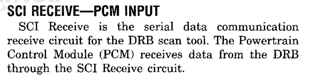
The DRB scan tool communicates with the PCM over the SCI circuits (Fig. 7). The SCI link does not use an interrupt to receive: the periodic interrupt tail polls the receive flag (01E14E), and the transmit routine waits for the transmitter before it writes each byte (8-7 Scan Tool Commands).
The program also holds a table stream on vector 4E. Its setup routine (00EC08) selects one of five address lists through the pointer table at ROM F659, clears the list position at F8345, writes interrupt vector 4E and enables the transmit interrupt. No instruction in this image calls the setup routine and no command table holds its address, so the transmit interrupt is never enabled and the stream is not sent.
When enabled, each transmit interrupt (00EC5A) reads the next list entry and sends one byte from working RAM. Addresses from F8000 up to, but not including, F8A05 are permitted. The stream ends when the next entry is FFFF or after 32 positions; an address outside the permitted range sends zero and ends the stream. At the end the handler disables the transmit interrupt. The stream reads only the listed RAM bytes. Refer to 8-1 Diagnostic Overview.
Fig. 7 SCI Receive (Group 14)
FAULT TRAPS
Each of the 248 fault slots leads to a short trap entry that stores a marker byte at F8A06 and jumps to the trap loop (021954). The marker is the vector number; the 235 unused slots share the default entry (02194A), which stores FF. The bus-error entry (0218CA) reloads the RAM base before it stores its marker. The trap loop clears port C bits 80 and 08 and repeats the port write indefinitely (Fig. 8). A trap does not return to the interrupted work.
The marker is a CPU exception number. It is not a diagnostic trouble code and is not a blink code. Refer to 8-2 Fault Reporting.
The scheduler releases three periodic groups of jobs, reloaded every 22, 172 and 1953 scheduler ticks (1-3 Job Scheduling). This section describes the smaller jobs that collect readings, keep counters and prepare output requests. The larger control functions have their own sections.
A job runs on every visit of its group, but most jobs test a counter, a flag or the command queue first and return without change when the test fails. The fast group calls its jobs through four wrapper routines. The medium and slow groups call each job from its own schedule record (Fig. 1).
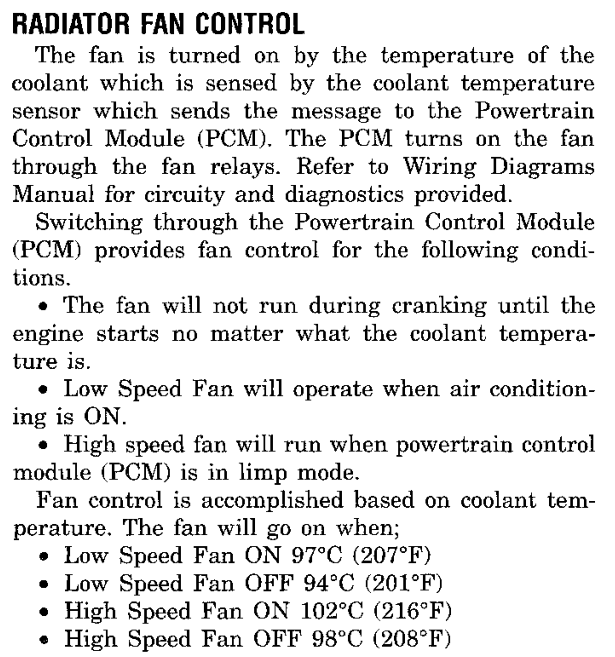
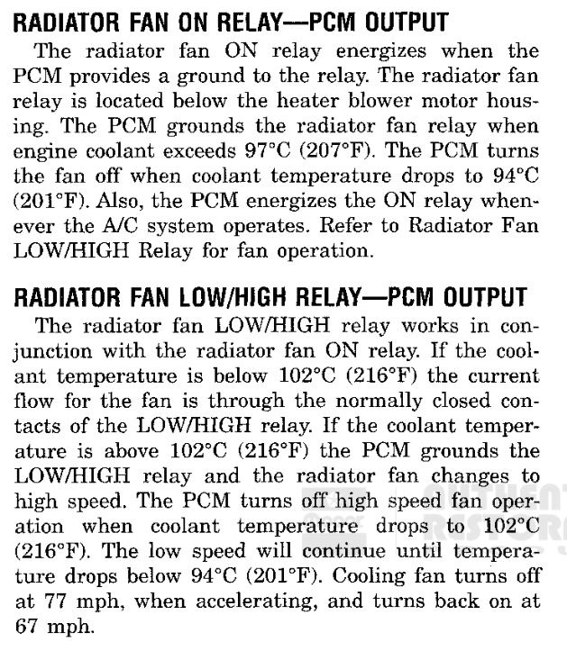
The PCM controls the radiator fan through two relays: the radiator fan ON relay and the radiator fan LOW/HIGH relay (Fig. 5). The fan job (01FA22) runs last in the slow group. It holds the ON relay request in F8107, bit 40, and the LOW/HIGH relay request in F8108, bit 01. The job compares the coolant value against calibrated pairs of thresholds, and the pair in use depends on road speed and on the present state of each request (Fig. 2).
The job returns without change when calibration option 2709 bit 80 is set, or when F8128 bit 08 is set. While the engine-running flag F80D1.40 is clear, the job sets F8107.40, so the fan does not run during cranking. When the coolant sensor fault flag F8808.80 is set, the job clears F8107.40 and moves to high speed, the limp-mode operation the manual describes (Fig. 4).
In normal operation, and with option 2709 bit 40 set, the high-speed stage is tested first. Below the road-speed threshold, the LOW/HIGH request is applied at 102 °C and released below 98 °C. Release sets F8108.01 and clears F8107.40, so the fan returns to low speed. The change to high speed is delayed: each pass decrements a countdown at F868C, loaded with 4, and F8108.01 clears only when the countdown reaches zero.
While the LOW/HIGH request is released and coolant is below the high-speed threshold, the low-speed stage runs. Below the road-speed threshold the job clears F8107.40 at 97 °C and sets it again below 94 °C (Fig. 3). These are the fan ON and OFF temperatures documented in the service manual. When F810B bits 02 and 04 are both set, the job requests low speed without testing coolant.
Each stage keeps its own road-speed flag (F8674.04 for the low-speed stage, F8674.02 for the high-speed stage). The flag sets below raw speed B4 and clears only at C8, so the band does not cycle. Above the threshold the job uses a second pair of temperatures, 184 °C and 190 °C, which releases the fan at road speed. The manual documents this as the fan turning off at 77 mph and back on at 67 mph.
The ON and LOW/HIGH relay requests leave the PCM through the output-command service (5-1 Output Commands). The PCM grounds the ON relay on circuit C27 and the LOW/HIGH relay on circuit C137.
01FAAABRCLR 0x674,Z,#0x4,0x01fab6; speed band flag01FAB0LDAA 0x271401FAB6LDAA 0x271301FABALDAB 0xa6,Z01FABECMPA 0xa4,Z; road speed01FAC4BSET 0x674,Z,#0x401FAC8BRSET 0x107,Z,#0x40,0x01fad6; fan on?01FACECMPB 0x2715; off below01FAD2BCS 0x01fb3e01FAD6CMPB 0x2716; on at or above01FADABCC 0x01fb22
Fig. 3 Low-Speed Stage ThresholdsFig. 4 Radiator Fan Control (Group 7)Fig. 5 Radiator Fan Relays (Group 14)
COUNTERS AND CORRECTIONS
Temperature filters. The temperature filter job (01391E) does its work only when the low six bits of counter F8097 equal 3E. On that visit it decrements the countdowns at F8024 and F83E3, runs the coolant temperature filter (01F926) and the intake air temperature filter (01F8BC), and calls the RPM-drop fuel preparation (1-6 Supporting Jobs). While the engine is stopped it also gives the blink-code formatter (013EF4) its turn (8-3 Blink Code Display).
Running age. The running-age job (0139F4) increments the counter at F80C4 on each slow-group visit while the engine-running flag is set. The counter stops at FF. The engine-speed routine clears it when the engine returns to the startup-fuel phase (2-1 Engine Position and Timing).
The running-age correction (013720) reads that counter together with the coolant temperature recorded at start (F80A7). After a delay of 0 counts it takes a value from the curve at 32F1 and tapers it to zero over 0 further counts. The result is stored at F82D2. Both calibration values are zero in this image, so the routine stores zero on every visit (Fig. 6).
Injector offset. The medium-group fuel timer job (013426) reads the injector offset curve with the value at F816E and stores the curve result at F826F. The slow-group job 01365C sends that byte to the companion processor as command 1D, select 1D, when fewer than nine commands wait in the queue (F80E4). The command carries the curve result only. The medium-group job (013426) also forms the complete signed injector offset at F82B4 (3-1 Fuel Amount).
Two medium-group jobs queue requests to the companion processor through the command queue (029270). Each request is queued only when the queue has room. The status and configuration job (014136) sends command 2A, select 1E, which returns the value at F816E used by the injector offset curve. It also sends command 25, which returns F82D9, and a set of configuration requests. The bitfield job (018A7C) sends commands 7A, select 1D, and 69, select 1E, and decodes the returned bits through the tables at C26E and C274.
SHARED PORT AND SPEED SAMPLE SERVICES
Four request bits share pins on processor port GP. Inside the first fast wrapper (01FC58), the drive routine copies bits 3 to 6 of the request byte F8502 to PORTGP and makes those pins outputs. Two calls later, after the throttle reference and barometric pressure updates, the release routine returns the same pins to inputs (Fig. 8). The reverse lockout request travels on this port (6-3 Reverse Lockout).
In the second fast wrapper, the mismatch routine (01A058) compares PORTGP bits 5 and 6 with the request byte. A bit requested set that reads clear is latched in F84FE; a bit requested clear that reads set is latched in F84FF. The fault qualification routine (01A138) checks PORTGP bits 3 and 4 against their requests with the counters at F84EC and F84ED, and latches F8496 bits 01 and 02.
Speed sample expiry. The periodic interrupt service (028502) reloads a lifetime count at F80A3 with each fresh sample. The expiry job (01E114) decrements a nonzero count and returns. A visit that finds the count at zero clears the road-speed value at F80A4, the working words at F8135 and F8648, and flag F80D6.01. With option 2707 bit 02 set, it also loads FFFF into the words at F8084 and F8086 (6-1 Vehicle Speed Input).
RETAINED STATE
The power input job (013A66) follows a state machine driven by PORTF0 bit 01. On its hold paths it sums the 515 bytes of retained working memory F8802 to F8A04 (013D08) and stores the 16-bit sum at F8800. One path clears F89A6 before taking the sum. At the next reset, the startup code compares the sum with F8800: a match preserves retained state, and a mismatch reinitializes it (1-2 Startup and Initialization).
The PCM monitors both fan relay control circuits. An open or shorted circuit sets the code shown in Fig. 10.
Fig. 10 Fan Relay Circuit Codes (Group 25)
SPECIFICATIONS
DESCRIPTION
SPECIFICATION
ROM
Fan job option byte (bit 80 disables, bit 40 enables two speeds)
47
2709
Low-speed fan on at or above (below speed threshold)
97 °C
2716
Low-speed fan off below (below speed threshold)
94 °C
2715
Low-speed fan on at or above (above speed threshold)
190 °C
2718
Low-speed fan off below (above speed threshold)
184 °C
2717
High-speed fan on at or above (below speed threshold)
102 °C
271C
High-speed fan off below (below speed threshold)
98 °C
271B
High-speed fan on at or above (above speed threshold)
190 °C
271E
High-speed fan off below (above speed threshold)
184 °C
271D
Low-speed stage speed band, enter below / leave at (raw)
B4 / C8
2713–2714
High-speed stage speed band, enter below / leave at (raw)
B4 / C8
2719–271A
High-speed step countdown
4 passes
3D70
Running-age correction delay
0 counts
32EF
Running-age correction taper
0 counts
32F0
Coolant temperature is the stored value minus 64 °C. Road speed is the raw value of F80A4.
CIRCUIT
PCM CAVITY
FUNCTION
C27
C1-2
Radiator fan ON relay control
C137
C1-21
Radiator fan low/high relay control
1 - 61 · SYSTEM OVERVIEWSR
SUPPORTING JOBS
DESCRIPTION AND OPERATION
IDLE AIR CONTROL
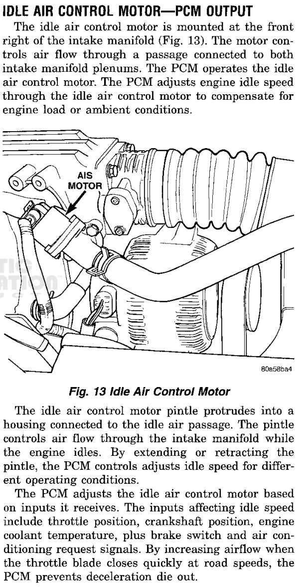
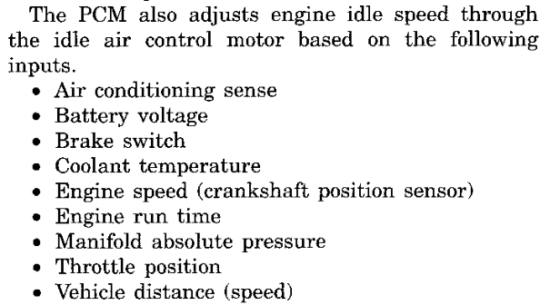
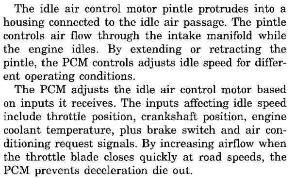
The PCM adjusts idle speed through the idle air control motor (Fig. 3). The software keeps two positions for the motor: the requested position at F8612 and the tracked position at F8810. The idle air service (021960) runs in the first fast wrapper. It updates the requested position from the engine-running state, the settle count at F8614 and its target, speed, pressure and A/C transition corrections (5-3 Idle Air Control).
At the end of each pass the service hands the request to the movement routine (0223B6) when the supply value at F816E is at or above 7A and engine speed is at or below 8000 rpm. The movement routine takes the difference between the tracked and requested positions and limits each move to 1F steps. While F8847 bit 80 is set, a move waits for the previous reply and is limited to 3 steps. The routine updates the tracked position by the amount moved and forms a command byte: the step count in the low five bits, the direction and mode in the upper bits (Fig. 2).
The queue routine (022432) marks the reply byte F8615 pending (FF) and sends the byte as command 22, select 1E. Calibration option 2708 bit 40 blocks the command; the bit is clear in this image. The reply is polled into F8615 by 022452. In the reset mode (F880F bit 08) the routine counts the tracked position down to zero.
When both positions are zero and F80D6 bit 01 is clear, the slow-group seed job (02246E) loads 2 into both and sets F880F bit 04. The three DRB idle air tests write the same requested position, so a test moves the motor through the normal movement path (Fig. 1).
Fig. 2 Idle Air Movement CommandFig. 3 Idle Air Control Motor (Group 14)
FUEL LEVEL INPUT
The fuel level job (0251FC) runs in the slow group. Calibration option 6F8C bit 80 selects the source of the reading. With the bit clear, as in this image, the job reads two values from the companion processor. Command 02, select 1E, returns F863E, the value the DRB reports as fuel level sensor voltage. Command 03, select 1E, returns F8670, the value the job filters.
A value of 97 or above is not filtered. After FF such visits in a row the job sets F8497 bit 40; after 1E visits below that value it clears the bit. While the bit is set the job saves the estimate, marks it FFFF and blends no new readings. When the bit clears and F880A bit 08 is clear, the saved estimate is restored.
The job smooths F8670 with the fractional filter (010048) and converts it through the curve at 214E. The result is stored at F8666 and at F863F, the fuel level percent reported to the DRB. A long-term estimate at F89A0 then follows the curve result through the weighted blend (025424): the old value is multiplied by the weight, the new result is added in the high byte, and the sum is divided by the weight plus one (Fig. 5).
The weight depends on road speed. The job counts consecutive visits at zero road speed in F8665. After 60 stopped visits the estimate blends with weight 9. Below that count, the weight is 300, and a reading that differs from the estimate by 33 or more is not blended.
025424LDD 0x9a0,Z; estimate025428EMUL ; times weight02542AADDA 0x666,Z; add result, high byte02542EADCE #0x0025432EDIV ; divide by weight + 1025434XGDX 025436STD 0x9a0,Z; new estimate02543ARTS
Fig. 5 Weighted Fuel Level Blend
CHARGING SYSTEM CHECKS
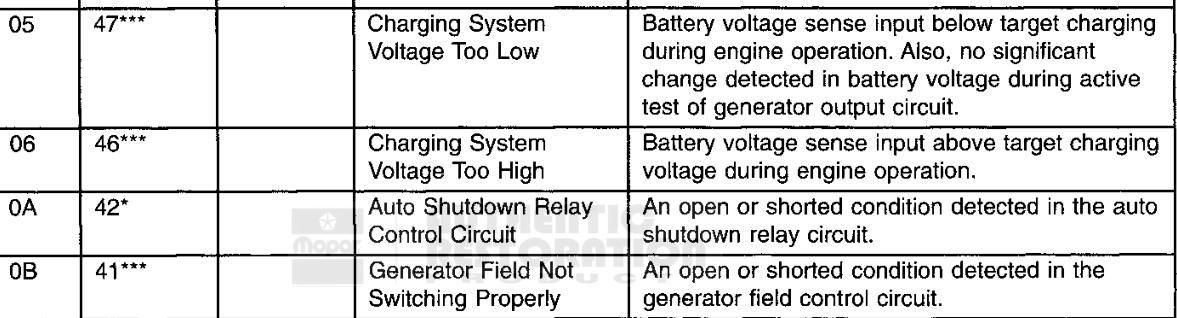
The software holds the charging target at F8351 and the supply value at F816E. The high-voltage check (019EAA) runs only while the engine runs and the target is nonzero. It returns 80, a failure, when the supply value exceeds the target by 10 or more, and 40, a pass, otherwise (Fig. 6). Its failure result is reported as code 46 (Fig. 11).
The deficit monitor (01AD1E) tests the target minus the supply value, engine speed and inhibit conditions. After its counters run, it sends companion test requests 81 and 82 and reads the response markers 2A and 2B at F8334 to set its result flags.
The battery temperature check (019E0A) tests the raw input at F8352 against 04 and FD. A value outside that range returns a low or high result and sends command 88, select 1E, with the substitute value 60; F848F bit 20 records that the substitute is applied. When the input returns to range, the check sends command 88 with zero and clears the bit. The low and high results are codes P1493 and P1492 (Fig. 12).
Rear oxygen targets. Two medium-group jobs, one per bank (01D386, 01D67E), write the oxygen targets F828E and F828F that the bank 1 and bank 2 fuel trim routines (011DF0, 0128CA) compare against the upstream sensors (3-2 Fuel Feedback). Rear-sensor feedback requires option 270A bit 40 for bank 1 and bit 10 for bank 2. The option byte is A1, so both jobs take their fallback target path. Oxygen heater fault patterns (019B54) set F8880 bit 01, which both rear-target jobs read as an inhibit.
Cylinder-pair inhibit. The slow-group inhibit job (01F874) runs when engine profile option 2707 has bit 02 or 04 set. Each of F880C bits 80, 40, 20, 10 and 08 adds one two-channel mask from ROM 08CE–08D7 to the inhibit word F817B (Fig. 7). The five masks cover all ten fuel channels. The running fuel routine (0109DC) and the starting fuel routine (011B14) test this word against the channel being prepared and set its pulse to zero on a match (3-1 Fuel Amount). The job only adds bits to the word.
Engine-speed drop. The RPM-drop preparation (014076) reads coolant temperature through the curves at 3558 and 357E and engine speed through the curve at 356B. It stores the results at F832A, F832E and F832C. The running fuel routine uses them to scale and cap the fuel term formed from filtered engine speed minus current engine speed (Fig. 9).
Several jobs keep values in the companion processor's memory. A write begins at 018776, which records the source, the 12-bit destination and the length, and sets the busy flag F867E bit 80. The write service (0187A0) streams the source in chunks of up to 16 bytes, accumulates a byte checksum and waits for the status reply at F868A. It resends a chunk when the reply is not recognized.
The slow-group expiry job (01F2E2) ends ISO 9141-2 sessions and actuator tests. While F834E bit 10, the ISO session flag, is set it decrements F834D. At zero it sends command 48, select 1E, with zero, clears the diagnostic state F8345–F834C, waits for the serial transmitter and returns the serial interface to the DRB rate (8-8 Generic OBD Requests). DRB sessions end through a separate inter-byte countdown, F834F, in the fast group (8-7 Scan Tool Commands).
A second countdown at F834C runs while an actuator test is active. With F8128 bit 08 set, expiry clears the bit and calls the actuator dispatch (00CF96). With F8128 bit 04 set, expiry calls the output restoration (00DCAE). While F8128 bit 08 is set, the fan job (01FA22) and the A/C clutch routine (018588) return without changing their requests, so the test keeps control of the output until it expires. The actuator tests are described in 5-1 Output Commands and 8-7 Scan Tool Commands.
DIAGNOSTIC TROUBLE CODES
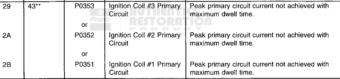
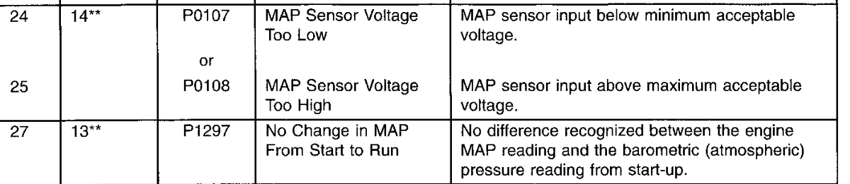
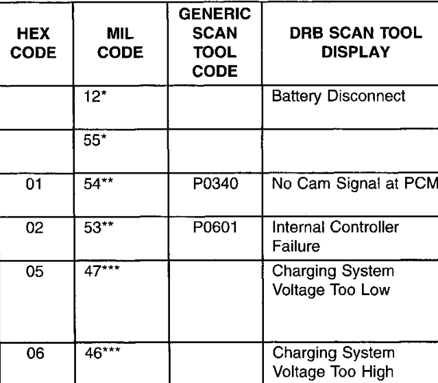
The service manual lists the following codes for the circuits in this section.
Fig. 10 Idle Air Control Code (Group 25)Fig. 11 Charging System Codes (Group 25)Fig. 12 Battery Temperature Codes (Group 25)
SPECIFICATIONS
DESCRIPTION
SPECIFICATION
ROM
Idle air seed position
2
3978
Idle air DRB test position
D2
3963
Idle air limited move (F8847.80 set)
3 steps
210B
Idle air move, minimum supply value
7A
3964
Idle air move, maximum engine speed
8000 rpm
0816
Idle air command option (bit 40 blocks)
08
2708
Fuel level source option (bit 80 local)
00
6F8C
Fuel level stopped visits
60
2148
Fuel level weight, stopped
9
2149
Fuel level weight, moving
300
214B
Fuel level blend difference limit, moving
33
2147
Charging high check margin
10
11F6
Battery temperature input low / high limit
04 / FD
11F0–11F1
Battery temperature substitute
60
11F2
Rear oxygen feedback option
A1
270A
Engine profile option
02
2707
Engine speed converts at 32 rpm per count. Supply, input and option values are raw bytes.
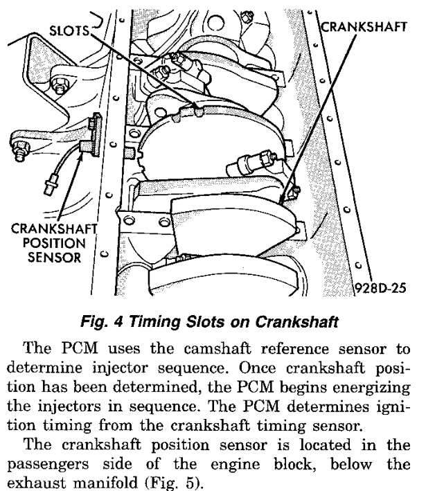
The PCM determines engine position from two inputs. The crankshaft position sensor reads slots cut into a disk on the crankshaft: five sets of two slots, ten slots in all. The camshaft position sensor reads a low and a high machined area on the camshaft drive gear, and its signal switches between approximately 0.3 volts and approximately 5 volts as the areas pass. The PCM determines injector sequence from the camshaft input and ignition timing from the crankshaft input (Fig. 1).
In the software, each engine event enters the capture interrupt routine (028F24). The routine reads the event timestamp, increments the event counter F8054, records a port state byte in F80C5, and reloads the two event watchdogs F80C6 and F80C7 from ROM 2100 and 2101. When the events stop, the watchdogs expire and the PCM retires its running state (2-2 Loss of Engine Events).
The routine then advances the event index F80BD. The index returns to zero after 20 events, the event count of the selected engine profile. The index and timestamp of each indexed event are pushed onto a six-record history at F80E5, which the speed calculation reads. Finally the routine copies the profile's event entry for the new index into F80BC. Each entry is one byte, and each bit requests a piece of work, as listed in the table below.
Fig. 1 Timing Slots on Crankshaft (Group 14)
EVENT SYNCHRONIZATION
The capture routine keeps the event index aligned with the engine using bit 08 of the port state byte. While the index is not synchronized, a change of that bit between two events sets the index directly: to 0 when the bit is clear and to 10 when it is set. The routine then marks the index synchronized (F80CE, bit 20).
Bit 08 of the event entries is clear in entries 0 through 9 and set in entries 10 through 19. After each index update the routine compares the port bit with bit 08 of the new entry. A disagreement outside a recheck clears the synchronized flag, sets the recheck flag F80CA bit 80 and loads the recheck count F80C2 with one less than half the event count.
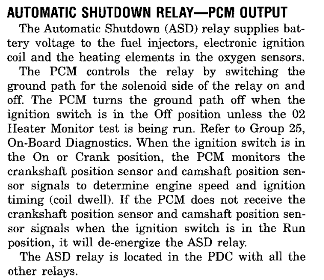
The first event after a stop takes a separate branch. It clears the event-loss request bits 40 and 80 of F8106 (bit 40 is the request the DRB ASD relay test operates), queues output command 04 and, when the queue allows, fuel-system command 2D with payload 60 (2-2 Loss of Engine Events). The service manual states that the PCM grounds the ASD and fuel pump relays after it receives the camshaft and crankshaft position inputs.
BIT
WORK REQUESTED BY THE EVENT ENTRY
01
Spark calculation: pending bit 02, or bit 10 in the spark-initialization phase
02
Fuel calculation: pending bit 01, or bit 08 in the startup-fuel phase
04
Engine speed calculation at this event
08
Compared with port bit 08 for synchronization
10
Event-interval history processing: pending bit 04
20
Selects fuel value group B (F82B2) for the interrupt fuel send
40
MAP conversion (010044); interrupt fuel send at high speed
80
Counts the event in F80BF, and in F80B6 while the engine is not running
ENTRY
BYTE
ENTRY
BYTE
0
A7
10
8F
1
70
11
58
2
87
12
AF
3
50
13
78
Event entries start at ROM 0718. Entries 4 through 9 repeat entries 0 through 3, and entries 14 through 19 repeat entries 10 through 13.
The even entries request the fuel and spark calculations and the speed calculation, so ten of the twenty events request fuel and spark. The odd entries request the MAP conversion, the event-interval history processing and the interrupt fuel send. Bit 20 alternates from one fuel-send entry to the next, so successive sends alternate between groups A and B.
ENGINE SPEED
The periodic interrupt (028502) calls the engine-speed routine (026CFC) whenever a captured event is waiting. The routine calculates speed at an event whose entry carries bit 04, or at the previous event when maintenance has fallen behind. It subtracts the timestamp recorded 2 events earlier from the newest timestamp, scales the 32-bit profile constant and the elapsed time down together until the time fits in 16 bits, and divides (Fig. 2). The quotient is the engine speed word F805A, in units of 1/8 rpm.
The same routine maintains the engine phase flags in F80D1 once speed calculation is ready (F80CF, bit 02) and F810B bit 01 is set (Fig. 3).
In the startup-fuel phase (bit 80), engine speed at or above 400 rpm sets the engine-running flag (bit 40) and the running-entry event (bit 01), ends the startup-fuel phase and clears the running timer F8096. Outside the startup-fuel phase, speed below 150 rpm returns it to the startup-fuel phase. That path clears the running flag, clears F80C4 and F80B6, saves the coolant reading F80A6 in F80A7 and stores the result of coolant curve 2721 in F813A.
In the spark-initialization phase (bit 20), speed below 450 rpm reloads the qualification counter F80B7 with 4. At or above that speed each pass decrements the counter. When it reaches zero, the routine sets the post-crank qualified flag (bit 10) and the spark run-up flag (bit 08) and ends the spark-initialization phase. With the phase clear, the routine compares the D register with 04B0. D holds the engine speed word, or the coolant-curve result on a pass that has just returned to the startup-fuel phase. A lower value clears the post-crank qualified flag, restores the spark-initialization phase and sets F80D5 bit 80, so the next spark-initialization command carries FF. The spark modes that follow from these flags are described in 4-1 Spark Timing.
For each waiting event, the engine-speed routine reads the event entry and sets pending-work bits in F80D2 (Fig. 4). The phase flags choose between the startup and the ordinary calculations. The pending-work dispatcher (028992) takes the lowest set bit, clears it, calls its handler through the table at ROM 0478, and scans again until no bit remains. Pending bits combine: one bit can stand for several events.
The fuel calculation stores two prepared values, group A in F82B0 and group B in F82B2. Below 5500 rpm the fuel calculation sends its own command 13. At or above that speed, the capture interrupt sends the prepared value itself on each event whose entry carries bit 40, choosing the group with bit 20. Fuel amount is described in 3-1 Fuel Amount.
FIRING ORDER AND CYLINDER OUTPUTS
At reset (020000) the PCM reads the engine profile selector at ROM 2707. Value 02 selects the V10 profile at ROM 06CA and the fuel mask table at ROM 08BA, and their pointers are saved in F8058 and F8177.
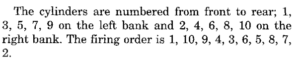
The cylinders are numbered front to rear, 1, 3, 5, 7, 9 on the left bank and 2, 4, 6, 8, 10 on the right bank. The firing order is 1, 10, 9, 4, 3, 6, 5, 8, 7, 2 (Fig. 6). The profile stores this order at ROM 06E4 as cylinder indexes counted from zero (Fig. 7).
Fig. 6 Cylinder Numbering and Firing Order (Group 9)
The ten fuel-output masks at ROM 08BA follow the same sequence, rotated by one position. The normal and startup fuel calculations index the masks with the fuel cursor F811E and test the selected mask against the fuel inhibit words F8179 and F817B, and a match zeroes the prepared fuel value. The capture routine sets the cursor when it synchronizes the event index and returns it to zero when the index wraps.
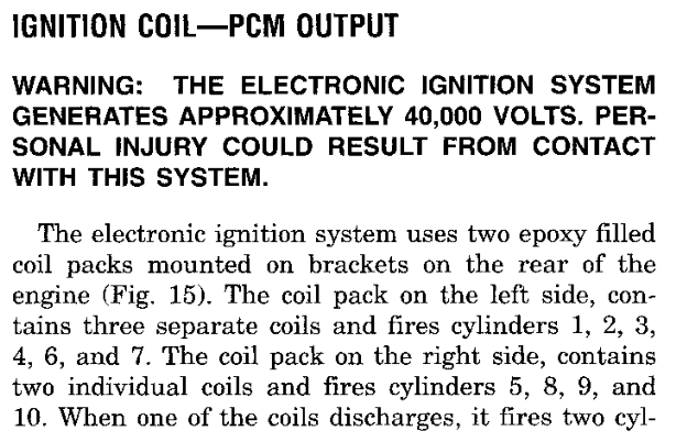
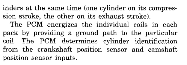
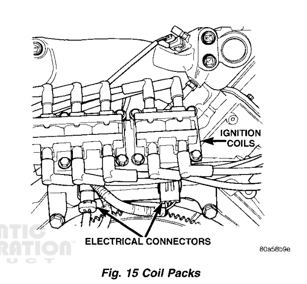
The ignition system uses two coil packs: three coils in the left pack fire cylinders 1, 2, 3, 4, 6 and 7, and two coils in the right pack fire cylinders 5, 8, 9 and 10. Each coil fires two cylinders at once, one on its compression stroke and the other on its exhaust stroke (Fig. 9). In the firing order, the two cylinders of one coil are five positions apart: 1 and 6, 10 and 5, 9 and 8, 4 and 7, 3 and 2.
The five cylinder-pair masks at ROM 08CE use the same spacing. Each mask joins two fuel-mask bits that sit five firing positions apart. The inhibit-mask merge (01F874) adds the selected pair masks to the inhibit word F817B; together the five masks cover all ten bits.
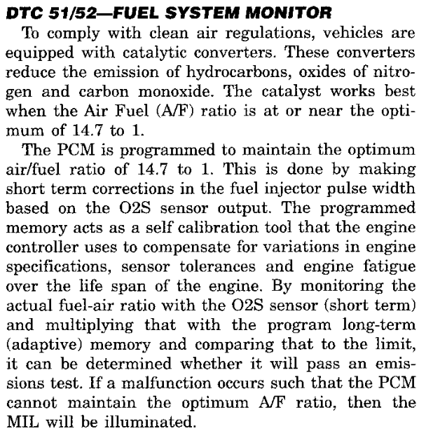
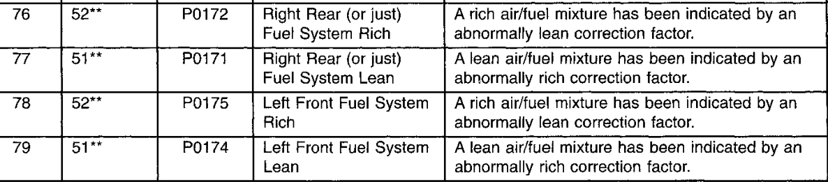
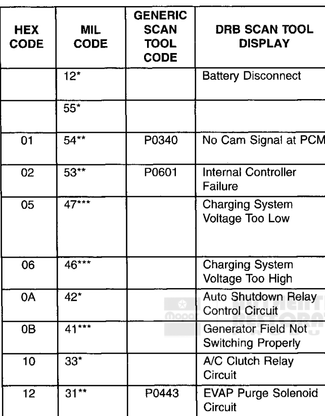
The service manual lists two trouble codes for the engine position inputs (Fig. 12, Fig. 13). The PCM code catalog at ROM 1222 holds both. Its record number matches the manual's hex code, and each record carries the generic code and the blink code.
Fig. 12 No Cam Signal at PCM (Group 25)Fig. 13 No Crank Reference Signal at PCM (Group 25)
The PCM confirms that the engine is turning by watching for engine events. Each event enters the engine event capture interrupt (028F24), which records the event timing, marks event activity and reloads two watchdog counters: F80C7 from 80 counts and F80C6 from 73 counts. While events keep arriving, both counters are refilled before they run out (Fig. 1). Engine position and the event pattern are described in 2-1 Engine Position and Timing.
The watchdog check (013E3E) runs in the fast job schedule through 01FCBC, which releases it every 22 scheduler ticks (1-3 Job Scheduling). Counter values are counts of these checks. The two counters expire on different boundaries:
F80C7, immediate path. Each check decrements a non-zero F80C7. The check that takes it from 1 to 0 performs loss handling at once.
F80C6, armed path. This path arms only while the engine running flag F80D1.40 is set and the high byte of the runtime word F8096 has reached 4. The check then sets the arm flag F80CE.01. An armed check decrements a non-zero F80C6 and returns. The next armed check that finds F80C6 already at zero performs loss handling.
The readable C in Fig. 2 matches the original instructions in every one of 3,072 checked cases.
Fig. 1 Engine Event Watchdog Path
RUNNING STATE RETIREMENT
Both expiry paths retire the running state so that other jobs stop treating the engine as turning. Each path clears the engine speed words F805A–F805D, the runtime word F8096 and F817D, clears the running flag F80D1.40 together with F80D1.10, and sets F80D1.80 and F80D1.20. Each path also clears the event state bits F80CE.20 and F80CE.10 and the bits F80CF.02 and F80CF.01.
The paths differ in detail. The immediate path also clears the spark target F83D5, the delivered spark value F83D6 and the final spark value F83D9 (4-1 Spark Timing), and clears F80CF.08 and sets F8847.80 only when F80CE.20 or F80CE.10 was set. The armed path first saves the high byte of F8096 to F899F, clears its own arm flag F80CE.01, and always clears F80CF.08 and sets F8847.80. Both paths then jump to the shared loss output tail at 013DD6.
Because F80CE.10 is cleared, the next engine event is handled as a first event. That branch of the capture interrupt restores the output requests, as described under Recovery.
The service manual states that the Automatic Shutdown (ASD) relay supplies battery voltage to the fuel injectors, ignition coils and oxygen sensor heaters, and that the PCM de-energizes the ASD relay when it does not receive the crankshaft and camshaft position signals with the ignition switch in Run (Fig. 3). With the key on and the engine not running, the ASD and fuel pump relays de-energize after approximately 1 second (Fig. 5).
In the software, the loss output tail at 013DD6 turns the loss into output requests (Fig. 4). If F8106.40 is already set, the loss requests are already in place and the tail returns. Otherwise it sets request bits F8106.80 and F8106.40, sets F848E.20, and sets F8108.04 because ROM 2708 bit 40 is clear in this image (08). It then queues output command 2D with payload 64 and output command 04 carrying the F8106 request byte, and copies F8106 to its shadow F8103 so that the changed-output service (029AFC) does not send it again. When F8541.10 is set, the tail sends command 04 only. When F851E holds EC13 with F8522.04 and F853F.20 set, the tail skips the request bits and sends the two commands directly. The DRB ASD relay test toggles the same bit, F8106.40 (see Diagnosis and Testing). Output commands are described in 5-1 Output Commands.
EVENT-LOSS OUTPUT SERVICE · 013D90complete routine
013D90BRSET 0x128,Z,#0x8,0x013e3c; diagnostic mode013D96BRSET 0x497,Z,#0x80,0x013da8; recovery013D9CBRSET 0xd1,Z,#0x40,0x013da8; running013DA2LDAA 0xc7,Z; F80C7 expired013DA6BEQ 0x013dd6013DD6LDD 0x51e,Z; EC13 test state013DDACPD #0xec13013DDEBNE 0x013dec013DE0BRCLR 0x522,Z,#0x4,0x013dec013DE6BRSET 0x53f,Z,#0x20,0x013e0a013DECBRSET 0x106,Z,#0x40,0x013e3c; latched013DF2BSET 0x106,Z,#0xc0; set F8106.C0013DF6BSET 0x48e,Z,#0x20013DFABRSET 0x2708,#0x40,0x013e04; ROM 2708.40013E00BSET 0x108,Z,#0x4; set F8108.04013E04BRSET 0x541,Z,#0x10,0x013e1e013E0ALDAB #0x64; payload 64
Fig. 4 Scheduled Entry and Loss Output Tail
SCHEDULED LOSS SERVICE
The event-loss output service (013D90) also runs on its own, every 1953 ticks in the slow job group (1-3 Job Scheduling). It does nothing while the diagnostic-mode bit F8128.08 is set. While the engine running flag F80D1.40 or F8497.80 is set, or while F80C7 is still counting, it enters the recovery gate. When F80D1.40 and F8497.80 are clear and F80C7 has reached zero, it enters the loss output tail. This service keeps the loss requests in force after the watchdogs have expired, and clears them through the recovery gate once F80D1.40 or F8497.80 is set or F80C7 is reloaded.
Fig. 5 Ignition Switch On (Zero RPM) Mode (Group 14)
RECOVERY
Two paths remove the loss requests. The service manual states that the PCM energizes the ASD and fuel pump relays after it receives the camshaft and crankshaft position signals (Fig. 6).
First engine event. When an event arrives with F80CE.10 clear, the capture interrupt sets F80CE.90, clears F8106.40 and F8106.80, and clears F8108.04. It sends output command 04 with F8106 and copies the byte to its shadow. When F80E4 is below 9 it queues command 2D with payload 60, and otherwise it sets F80CC.02. When F80CC.40 is set, it sets F80CC.02 and sends neither command.
Recovery gate. The gate (013DA8) returns at once when F8106.40 is already clear. Otherwise the recovery commands (013DAE) clear F8106.C0 and F8108.04, load F80C7 with 5 so that the immediate watchdog expires again unless events refresh it, queue command 2D with payload 60, and send command 04 with F8106. When F851E holds EC13 with F8522.04 set, the recovery commands skip the F80C7 reload and the command 2D request.
CAUTION: The service manual states that during the ASD Fuel System Test the ASD relay and fuel pump relay remain energized for 7 minutes, until the test is stopped, or until the ignition switch is turned Off.
DIAGNOSTIC TROUBLE CODES
The service manual lists the following codes for the signals and relay circuits in this section.
HEX
BLINK
P CODE
DESCRIPTION
28
11
No crank reference signal at PCM
01
54
P0340
No cam signal at PCM
9D
11
P1391
Intermittent loss of CMP or CKP
0A
42
Auto shutdown relay control circuit
65
42
Fuel pump relay control circuit
Service manual group 25, pages 25-3 to 25-6. Fault reporting is described in 8-2 Fault Reporting.
SPECIFICATIONS
DESCRIPTION
SPECIFICATION
ROM
Immediate watchdog F80C7 reload at each engine event
80 counts
2101
Armed watchdog F80C6 reload at each engine event
73 counts
2100
Armed path enable, runtime word high byte at or above
4
2103
Configuration byte (bit 40 clear: F8108.04 follows loss and recovery)
08
2708
Watchdog check interval
22 ticks
08DC
Loss output service interval
1953 ticks
090A
Watchdog counts are counts of watchdog checks.
Fig. 9 Automatic Shut Down Relay Circuit (Group 8W-30)
CIRCUIT
PCM CAVITY
FUNCTION
K51
C1-3
Automatic shutdown (ASD) relay control
A142
C1-12
ASD relay output / PCM sense
K31
C1-19
Fuel pump relay control
SR3 · FUEL SYSTEM3 - 1
FUEL AMOUNT
DESCRIPTION AND OPERATION
FUEL CALCULATION
The PCM controls injector pulse width by switching the ground path to each injector. Engine speed and manifold absolute pressure are the primary inputs that determine pulse width (Fig. 1). The PCM software follows the same plan: a base quantity is read from a speed-by-pressure map, corrected, tested against the fuel-cut requests and handed to the output command path as a raw fuel word (Fig. 2).
Two routines calculate fuel. Each engine event whose profile entry carries bit 02 sets a pending task, and the task dispatcher (028992) runs one of them. While the startup-fuel phase flag F80D1 bit 80 is set, the event schedules the startup fuel routine (011B14). Once the engine-running latch clears that phase, the same event schedules the running fuel routine (0109DC). Engine events and the running latch are described in 2-1 Engine Position and Timing.
The startup routine builds its quantity F82AE from a coolant curve, a pressure correction, a correction against an event counter and a speed correction, then sends it through the same fuel command as the running routine.
The running fuel routine converts its two inputs into map coordinates. The engine speed word F805A is rounded to its high byte and normalized through the engine speed axis at ROM 2814 into F8170. The filtered manifold pressure byte F804E is normalized through the pressure axis at ROM 284A into F816F. The word-grid lookup (029EB2) then interpolates the selected map between its four surrounding cells and stores the base fuel word in F82A0 (Fig. 3).
The map holds 17 engine speed rows by 9 pressure columns of 16-bit cells. Interpolation is integer arithmetic: each coordinate is scaled by the table dimension less one, the high byte selects the cell and the low byte is the fraction. Each of the two bounding rows is interpolated and rounded, then the two results are interpolated and rounded again. The lookup method is described in 9-2 Fuel and Starting Tables.
Two base fuel maps are present, A at ROM 2B82 and B at ROM 2CB8. Map B is selected when either bit of mask 14 in F80CB is set and both bits of mask 05 in F880B are clear; otherwise map A is selected. In this calibration the two maps hold identical values, so the selection does not change the base fuel word.
RUNNING FUEL CALCULATION · 0109DCmap select and lookup
011218LDX #0x2b82; map A01121CBRCLR 0xcb,Z,#0x14,0x011232; mode bits 14011222BRSET 0x80b,Z,#0x4,0x011232; F880B bit 04011228BRSET 0x80b,Z,#0x1,0x011232; F880B bit 0101122ELDX #0x2cb8; map B011232LDAA 0x170,Z; speed coordinate011236LDAB 0x16f,Z; pressure coordinate01123AJSR 0x01003c; word grid lookup01123ESTE 0x2a0,Z; base fuel word
Fig. 4 Base Fuel Map A (Map B at 2CB8 is identical) — complete entry 9-2, Fig. 1
FUEL CORRECTIONS
The running routine applies a series of calibrated corrections to the base word. An intake air temperature curve (ROM 2E01) produces F826B. The enrichment grid at ROM 2E4F, indexed by the same speed and pressure coordinates, supplies an enrichment factor; a second enrichment curve against engine speed (ROM 2F11) serves an alternate path. The bank 1 and bank 2 oxygen-feedback routines (011DF0, 0128CA) maintain the short-term and long-term trims. The running routine applies the bank 1 or bank 2 trims according to the active fuel group, F80BC bit 20. Fuel feedback is described in 3-2 Fuel Feedback.
An injector offset is added to the fuel quantity. The fuel timer service (013426) reads the offset curve at ROM 2DEE into F826F, multiplies the result by four and adds the signed base offset at ROM 2B75. The sum saturates at the signed 16-bit limits and is stored in F82B4 (Fig. 5). The running routine adds F82B4 to the fuel quantity. A separate service (01365C) sends the curve byte F826F on select 1D when the command queue has room.
The prepared value is then held at no less than the fuel floor at ROM 2B79 before the fuel-cut gates are tested.
READABLE Cviper_fuel_ignition.c
int16_t viper_compute_injector_offset(uint8_t curve_result, int16_t base_offset)
{
    int32_t sum = (int32_t)curve_result * 4 + base_offset;
    if (sum > INT16_MAX) return INT16_MAX;
    if (sum < INT16_MIN) return INT16_MIN;
    return (int16_t)sum;
}
Fig. 5 Injector Offset Arithmetic
DECELERATION FUEL CUT
During a hard deceleration with a closed throttle, the PCM momentarily turns off the injectors (Fig. 6). The cut-request routine (0134A6) decides when to latch this condition, and the running fuel routine decides when to release it (Fig. 7).
Entry is qualified first. The high byte of the engine-running timer F8096, the pressure value F8804, intake air temperature, the vehicle speed byte and coolant temperature must each be at or above its calibrated minimum. Engine speed must then be strictly above the idle speed target F811C plus the entry margin. The margin is read from the curve at ROM 390E against coolant temperature; refer to Specifications.
When the throttle is off idle (F80D6 bit 80), the routine reloads the entry delay F82D7. At closed throttle, the working fuel word for the active group must be below the entry fuel ceiling and the re-entry lockout F80B3 must be zero. Each qualifying pass then decrements the entry delay. The pass that finds the delay already at zero sets the deceleration cut flag F82D3 bit 10, sets its mirrored request F82D6 bit 10 and loads the hold count F829C (Fig. 8).
While the latch is set, the running fuel routine saves the prepared fuel word and tests three resume conditions: engine speed at or below the idle target plus the resume margin from the curve at ROM 392A, the throttle off idle, or the working fuel word for the active group at or above the resume fuel threshold. Any one condition clears both flags, sets spark flag F80D4 bit 01, reloads the re-entry lockout F80B3 and restores the saved fuel word. Otherwise the fuel word is set to zero for that pass.
A temporary deceleration profile with its own entry and resume curves (ROM 8069 and 8085) is selected by F883B bit 80. The reset routine enables it only when ROM 8068 bit 80 is set; that byte is 00 in this calibration.
The same routine maintains two speed-limit requests. The engine speed limit sets F82D3 bit 01 and request F82D6 bit 40 when engine speed exceeds the limit at ROM 3955. While the request is set, the limit is lowered by the release drop at ROM 3953, so the request clears only when speed falls to the lower value. When status bit F8808 bit 20, F8808 bit 40 or F8809 bit 20 is set, the limit is taken from ROM 6009 instead, with the same release drop (Fig. 11).
The combined limit sets F82D3 bit 02 and request F82D6 bit 80 only when engine speed exceeds the limit at ROM 3959 and the filtered road speed word F8135 exceeds the limit at ROM 395B. Both limits drop by their release values while the request is set.
The running fuel routine sets the prepared fuel word to zero whenever F82D3 bit 01 or bit 02 is set, or when external status bit F865E bit 20 or F8584 bit 20 is set. Bit 20 of F80BC selects the group fuel word, F82B0 or F82B2, that receives the result. The other group word receives the same value while its counter (F8296 for F82B0, F8297 for F82B2) is zero; ROM 270D bit 01 suppresses this copy, and that byte is 00 in this calibration. Below the engine speed threshold at ROM 2138, the running routine queues fuel command 13 on select 1D itself. At and above that threshold, the engine-event interrupt (028F24) queues the same command from the stored word of the active group whenever F80BC bit 40 is set. The command queue is described in 5-1 Output Commands. The PCM grounds the ten injector drivers in sequence (Fig. 12).
Fuel command passed to engine-event interrupt at or above
5500 rpm
2138
Prepared fuel floor
445 counts
2B79
Injector offset base value
179 counts
2B75
Decel entry, running timer high byte at least
10 counts
3946
Decel entry, pressure value F8804 at least
128 counts
394A
Decel entry, intake air temperature at least
-50 °C
3947
Decel entry, vehicle speed byte at least
64 counts
3948
Decel entry, coolant temperature at least
60 °C
3949
Decel entry margin above idle target (0 °C and 80 °C)
921 rpm
390E
Decel entry fuel word ceiling
864 counts
394F
Decel entry delay reload
255 passes
395F
Decel hold count reload
91 counts
334C
Decel resume margin above idle target (0 °C and 80 °C)
880 rpm
392A
Decel resume fuel word threshold
1024 counts
3951
Decel re-entry lockout reload
254 counts
394B
Engine speed limit, request sets above
6200 rpm
3955
Engine speed limit release drop
400 rpm
3953
Status-selected engine speed limit
3200 rpm
6009
Combined limit, engine speed above
7000 rpm
3959
Combined limit, engine speed release drop
400 rpm
3957
Combined limit, road speed word above
16320 counts
395B
Combined limit, road speed release drop
1920 counts
395D
Engine speed words convert at 8 counts per rpm; a single speed byte converts at 32 rpm per count. Temperatures are the stored value minus 64 °C. Fuel words are raw counts.
In CLOSED LOOP modes the PCM fine-tunes injector pulse width from the upstream heated oxygen sensor inputs (Fig. 1). The software performs this work in two bank trim routines, one for each cylinder bank: 011DF0 for bank 1 and 0128CA for bank 2. Bank 1 reads its upstream oxygen value from F8038; bank 2 reads F803A.
The fuel pulse width routine (0109DC) calls both trim routines after it has selected the base fuel value (3-1 Fuel Amount). Each call is enabled by a configuration bit in ROM 270A: bit 80 enables the bank 1 routine and bit 20 enables the bank 2 routine (Fig. 2). This calibration stores A1, so both banks run. When RAM flag F8558 bit 10 is set, the bank 2 call also requires ROM 270D bit 40 to be clear; this calibration stores 00 at that address, so the call is always made.
0113C4BRCLR 0x270a,#0x80,0x0113ce; bank 1 enable0113CAJSR 0x011df0; bank 1 trim0113CEBRCLR 0x270a,#0x20,0x0113e4; bank 2 enable0113D4BRCLR 0x558,Z,#0x10,0x0113e00113DABRSET 0x270d,#0x40,0x0113e4; alternate layout0113E0JSR 0x0128ca; bank 2 trim
Fig. 2 Bank Trim Calls and Their Configuration Bits
The short-term correction for each bank is held in F828C (bank 1) and F828D (bank 2), and the long-term correction in F827E (bank 1) and F8280 (bank 2). The diagnostic data services report these four values as standard parameters 06 to 09, and report the two upstream oxygen values with their short-term corrections as parameters 14 and 18.
Fig. 3 Fuel Feedback Path (one bank)
LEARNING GATE AND FEEDBACK CONDITIONS
Each bank trim routine opens with a learning gate (Fig. 4). The gate tests the shared upstream inhibit flag F8880 bit 02 together with stored fault-state fields at F880C, F880D and F880E. When the inhibit flag or a selected F880D bit is set, the routine sets its inhibit marker (F8175 bit 08 for bank 1, F8176 bit 08 for bank 2). On any gate condition, the routine clears the bank's 27 learned entries (F889A for bank 1, F88B5 for bank 2) and branches to its fallback path. The fallback path clears the short-term correction and resets the working terms of the bank.
With the gate passed, the routine qualifies the upstream oxygen value. A value below 3E (ROM 3348) reloads a holdoff count from ROM 334E (bank 2: ROM 334F). A value at or above the limit sends the routine to the fallback path once the holdoff count is zero.
Engine speed is tested next, with hysteresis. Above 3808 rpm the routine sets its speed flag (F82D4 bit 01 for bank 1, F82D5 bit 01 for bank 2) and takes the fallback path. The flag clears only after engine speed falls to 96 rpm below the limit. Further state tests follow. Most divert the routine to the fallback path; two of them instead load a fixed short-term correction from ROM 338D or ROM 3352 and reset the working terms.
SHORT-TERM CORRECTION
The qualified oxygen value is converted through the curve at ROM 3704, shared by both banks, and the result (F8292 for bank 1, F8293 for bank 2) is compared with the bank's switching targets. One of those targets is the rear target value F828E (bank 2: F828F), written by the rear target routines 01D386 and 01D67E. The outcome of the comparison is held in the bank's feedback state byte, F82D4 or F82D5. Bit 02 of F82D4 is the bank 1 feedback state that the purge oxygen sequence also reads (5-2 Accessory and Evaporative Outputs).
Normal rear feedback is enabled by ROM 270A bit 40 for bank 1 and bit 10 for bank 2. Both bits are clear in this calibration, so the rear target routines run their fallback target handling.
The short-term correction is the signed sum of three working terms, F82A2, F8290 and F8286. The third term is the difference of two working values multiplied by the gain in ROM 35A3. The sum is limited to the range set by ROM 35AC and ROM 35AE for bank 1, and ROM 35AD and ROM 35AF for bank 2, before it is stored (Fig. 5).
Fig. 5 Short-Term Correction Sum and Limit, Bank 1
OXYGEN SENSOR STATE AND HEATER HISTORY
Two jobs in the fast supporting group (01FCF6) maintain the oxygen sensor state that the trim routines and monitors consume (1-6 Supporting Jobs).
The threshold tracking routine (0163C6) watches the rear bank 1 input F803C. A reading below 3D sets low flag F8568 bit 40 once its holdoff count, reloaded from ROM 7B82 (2), has expired; a reading at or above the threshold clears the flag and reloads the count. While the engine is running, the routine latches a low-to-high crossing of each enabled input: a reading below 0F arms the crossing, and a later reading at or above 28 completes it (Fig. 6). The bank 1 upstream crossing is always tracked; the rear bank 1 crossing is enabled by ROM 270A bit 20, which is set in this calibration.
OXYGEN THRESHOLD STATEviper_oxygen_state.c
static void low_holdoff(uint8_t *r, unsigned input, unsigned timer, uint8_t bit)
{
    if ((r[0x568]&bit)!=0) {
        if (r[input]>=0x3D) {r[0x568]&=(uint8_t)~bit;r[timer]=2;}
    } else if (r[timer]!=0) {
        uint8_t remaining=(uint8_t)(r[timer]-1);
        r[timer]=(remaining&0x80)!=0?0:remaining;
    } else if (r[input]<0x3D) r[0x568]|=bit;
}
static void low_then_high(uint8_t *r, unsigned input, unsigned state,
                          uint8_t seen_low, uint8_t completed)
{
    if ((r[state]&completed)!=0) return;
    if ((r[state]&seen_low)==0) {
        if (r[input]>=0x0F) return;
        r[state]|=seen_low;
    }
    if (r[input]>=0x28) {
        r[state]|=completed;
        r[state]&=(uint8_t)~seen_low;
    }
}
void viper_track_oxygen_threshold_state(uint8_t *r,uint8_t config_a,uint8_t config_d)
{
    low_holdoff(r,0x3C,0x556,0x40);
    if ((config_a&0x10)!=0) low_holdoff(r,0x3E,0x557,0x20);
    if ((r[0xD1]&0x40)==0) return;
    low_then_high(r,0x38,0x37A,8,4);
    if ((config_a&0x20)!=0) low_then_high(r,0x3C,0x37A,2,1);
    if ((config_d&0x40)!=0) low_then_high(r,0x3E,0x379,0x10,8);
}
Fig. 6 Oxygen Threshold Crossings and Holdoff
The heater history routine (019B54) reads the stored history of the four oxygen sensor heater codes and sets two shared inhibit flags. The upstream heater codes, P0135 and P0155, set F8880 bit 02, which the learning gate of both bank trim routines tests. The downstream heater codes, P0141 and P0161, set F8880 bit 01, which the rear target routines test. The routine recognizes exact combined history patterns: on every pass it sets each flag when its pattern is recognized and clears it otherwise.
The ASD relay supplies battery voltage to the upstream and downstream heated oxygen sensor heaters. The upstream sensor signals reach the PCM on circuits K241 and K41 (Fig. 7).
DIAGNOSIS AND TESTING
FUEL SYSTEM MONITOR
The fuel system monitor compares the short-term correction, combined with the long-term (adaptive) memory, against a limit (Fig. 8). In the software this is the rich/lean trim monitor 01C512, attached to descriptor C02E. It tests pressure, running and feedback state, then compares the signed long-term and short-term corrections of each bank (F827E with F828C, and F8280 with F828D) through staged countdowns. Its result bits 01, 02, 04 and 08 at F8157 select fault codes P0172, P0171, P0175 and P0174 through the code list at ROM 6DDE. The selector 0151D2 takes the lowest remaining result bit and returns its fault id for recording (8-2 Fault Reporting).
Fig. 8 DTC 51/52 — Fuel System Monitor (Group 25)Fig. 9 Fuel System Trouble Codes (Group 25)
MONITOR DESCRIPTORS
The detailed fault-monitor descriptors (Fig. 10) decide which monitor families the PCM schedules (8-1 Diagnostic Overview). In this calibration the enable mask allows the fuel system monitor (C02E). The oxygen-response descriptors C066 (018078, codes P0133, P0153, P0139) and C082 (0183EE, codes P0139, P0159) are not allowed, so their routines are not scheduled.
Feature configuration (bank 1 trim 80, rear feedback 40, bank 2 trim 20, rear bank 2 10)
A1
270A
Alternate layout configuration
00
270D
Upstream oxygen qualification limit (raw)
3E
3348
Oxygen holdoff reload, bank 1
3 counts
334E
Oxygen holdoff reload, bank 2
3 counts
334F
Feedback engine-speed limit
3808 rpm
3354
Feedback engine-speed hysteresis
96 rpm
3355
Short-term correction lower limit, bank 1 / bank 2 (signed)
81 / 81
35AC / 35AD
Short-term correction upper limit, bank 1 / bank 2 (signed)
7F / 7F
35AE / 35AF
Change-term gain
01
35A3
Rear low threshold (raw)
3D
7B81
Rear low holdoff reload
2 counts
7B82
Crossing arm threshold (raw)
0F
7BD3
Crossing complete threshold (raw)
28
7BD4
Engine speed converts at 32 rpm per count. Oxygen thresholds are raw input counts.
CIRCUIT
PCM CAVITY
FUNCTION
K241
C3-24
LEFT upstream oxygen signal
K341 coupe / K141 roadster
C3-25
RIGHT downstream oxygen signal
K41
C3-26
RIGHT upstream oxygen signal
K141 coupe / K341 roadster
C3-29
LEFT downstream oxygen signal
SR4 · IGNITION SYSTEM4 - 1
SPARK TIMING
DESCRIPTION AND OPERATION
IGNITION SYSTEM
The Viper uses a distributorless ignition system with two coil packs at the rear of the engine. The left pack holds three coils and the right pack holds two; each coil fires two cylinders at once, one on its compression stroke and one on its exhaust stroke (Fig. 9). The PCM grounds each coil through its own driver circuit on connector C3. Basic ignition timing is not adjustable: the PCM sets spark advance from intake air temperature, coolant temperature, engine speed, manifold vacuum and throttle position (Fig. 1).
The PCM software calculates a single spark advance value and hands it to the output system as command 24. The value is kept in half-degree counts before top dead center. The calculation runs as an engine-event task: each event whose profile entry carries bit 01 dispatches spark initialization (0100E8) while the spark-initialization phase flag F80D1 bit 20 is set, and the spark advance calculation (01015A) at all other times. Refer to 1-3 Job Scheduling and 2-1 Engine Position and Timing.
Fig. 1 Spark Advance Inputs (Group 8D)
SPARK MODES
Two mode flags in F80D4 choose the primary spark source before any correction is applied (Fig. 3).
Closed-throttle low-speed mode (bit 10). With the throttle at its closed reference, the mode sets when the engine speed byte (32 rpm per count) is at or below 46, and holds until the byte exceeds that value plus 3. Opening the throttle clears the mode. Entering the mode, or leaving it through the throttle, sets the transition request F80D5 bit 20. In this mode the primary source is the coolant curve at 2778 or 278B (Fig. 11).
Timed post-start mode (bit 40). Spark initialization clears the ramp value F83D3 and sends command 24 with a zero payload, or FF when F80D5 bit 80 is pending. It then arms the post-start mode when coolant temperature is from 10 °C up to 30 °C, loading the post-start timer F83E0 with 64 counts. The timer counts down only after the post-crank qualification flag F80D1 bit 10 is set. When it reaches zero the mode clears and the end-of-mode request F80D5 bit 40 is set. In this mode the primary source is the speed and pressure grid at 2995 (Fig. 10).
Engine speed and filtered manifold pressure enter the spark grids as coordinates F8170 and F816F, on a 17-point speed axis and a 9-point pressure axis. With neither mode flag set, the routine reads one of two base maps, 285D and 28F9 (Fig. 5), and stores the result in F83DB. Map 285D is used whenever F880B bit 01 or bit 04 is set; otherwise the choice follows the countdown F80AB and the state bit F80CB bit 10 (Fig. 4). In this calibration the two maps hold identical values. When the throttle-duration flag F80D4 bit 04 is set, the grid at 2A31 is added to the base value; the flag sets after the larger-opening throttle qualifier has persisted for more than 8 passes. Every cell of 2A31 is zero in this calibration.
When F80D4 bit 20 is set, two temperature corrections follow. Coolant temperature selects a row of grid 2ACD and intake air temperature a row of grid 2B21 (Fig. 12, Fig. 13); both use the pressure coordinate for the column. Their signed sum, saturated at 80 and 7E, is stored in F83DE. The fixed combined-mode value skips both corrections.
Fig. 5 Base Spark Map A (Map B Identical) — complete entry 9-3, Fig. 25
SPARK TARGET AND LIMITS
The routine adds the primary source, the base value, the post-start value, the temperature correction and the signed term F83E1. The running sum is set to 7E when the primary source and base value together reach 7F or when the last addition overflows, and to zero whenever an addition turns it negative. It then subtracts two retard terms, each with a floor of zero: a calibrated retard F83E5, and the shift-torque retard F8457 produced by 024AF4. The shift-torque path is enabled by ROM A009 bit 40, which is clear in this calibration (6-2 Transmission Controls). The result is the spark target F83D5 (Fig. 6).
A transition stage then carries the delivered value F83D6 toward the target. The low-speed mode request (F80D5 bit 20) and the end-of-post-start request (F80D5 bit 40) both route through this stage, which moves the value in calibrated steps rather than in one jump.
When its enable flag F80D4 bit 08 is set, the routine also computes an idle speed term. It takes the difference between engine speed F805A and the idle speed target F811C, in 2 rpm counts limited to FF, and reads curve 27C8 at or above the target or 27A2 below it (Fig. 14); ROM 270B bit 80 is set in this calibration and selects these two curves. The signed result F83DC is added to the delivered value, again held between 0 and 7E.
OVERRIDES, RUNUP AND COMMAND
Three override flags replace the calculated value outright: F8109 bit 02 substitutes F834A, F8109 bit 80 substitutes 28 half-degree counts, and F8128 bit 80 substitutes the value at ROM 403A. Without an override, while the runup flag F80D1 bit 08 is set, the ramp value F83D3 rises by 22 counts on each pass and is delivered in place of the target until it comes within two counts of it; the flag then clears and the target is delivered.
The final value is stored in F83D9, which the diagnostic timing-advance report (Mode 01 PID 0E) reads. The routine shifts it right one bit, so the command carries whole degrees, and queues it as command 24 with select 1E (Fig. 7). The coprocessor command service (029270) writes command 24 directly to transmit word FFD22 and sets pending bit 80, bypassing the general queue. Refer to 5-1 Output Commands.
Basic ignition timing is not adjustable. To check the commanded value, read the timing-advance parameter with a scan tool; it reports F83D9 in half-degree resolution. Engine speed, coolant temperature, intake air temperature, manifold pressure and throttle position all change the commanded value. Check those inputs first when timing is out of range. Refer to 7-1 Substitute Values.
DIAGNOSTIC TROUBLE CODES
The PCM monitors the primary circuit of each coil. A code sets when peak primary current is not reached within maximum dwell time (Fig. 15, Fig. 16). The PCM cannot detect an inoperative coil, fouled or worn spark plugs, cross firing, or open spark plug cables.
The PCM software separates the decision to operate an output from the command that operates it. Each control routine records its decision as a request bit in RAM. A separate output stage converts the requests into commands and passes the commands to the PCM output hardware. The service manual lists the outputs the PCM operates (Fig. 1).
Three request bytes, F8106, F8107 and F8108, hold the on/off requests that leave the processor through the command queue. A fourth byte, F8502, holds requests that are presented directly on a processor port (refer to Shared Port Outputs). Fuel pulse width and spark advance travel on their own command path (refer to Fuel and Spark Commands). The reset routine (020000) writes all four request bytes before the job schedule starts.
Each request bit has a normal control routine, and all but the malfunction indicator lamp bit have DRB test routines that write it, as listed below. The engine-event loss path (013D90) sets F8106 bits 40 and 80 when engine events stop, and the first engine event clears them again (2-2 Loss of Engine Events). Because ROM 2708 bit 40 is clear (08), the same paths also set and clear F8108 bit 04.
The changed-output service (029AFC) is the last call of the fast engine-control job group (01FC8E), so it runs after every control routine in that group has updated its requests (1-3 Job Scheduling). It handles the three request bytes in order, F8106, F8107, then F8108 (Fig. 2).
For each byte the service first checks the command queue. When the queue already holds nine commands, the service returns and the remaining bytes wait for the next pass. Otherwise it forms the payload from the request byte and compares the payload with its shadow byte. An unchanged payload sends nothing. A changed payload is copied to the shadow and queued as that byte's command (Fig. 3).
REQUEST
SHADOW
COMMAND
SELECT
F8106
F8103
04
1E
F8107
F8104
26
1E
F8108
F8105
04
1D
The shadow is written only when the command is queued, so a change held back by a full queue is sent on a later pass. A request that a control routine sets and clears again between two passes produces no command. The shadow bytes record the last payload queued for each request byte.
Until the engine has run, the service sends each byte with a startup mask applied: the payload is the request byte ANDed with the complement of ROM 270E, 270F or 2710. The service sets the pass-through latch, F811F bit 02, when the engine-running flag F80D1 bit 40 is set or the high byte of the engine-running timer F8096 is nonzero. With the latch set, the request bytes pass unmasked. The service sets this latch and never clears it.
The F8107 mask is 90. Before the latch sets, the shift indicator lamp bit 80 and the malfunction indicator lamp bit 10 are sent clear. The skip-shift solenoid bit 08 passes in both cases (Fig. 4).
Fig. 4 F8107 Payload With and Without the Startup Mask
COMMAND QUEUE AND TRANSFER
The command queue routine (029270, entered through 010028) receives a command record: a command number, a destination select and a payload. It files the record by command number. Command 24 (spark) has a dedicated one-word slot. Commands 13 (fuel) and 19 fill a dedicated two-word slot, with the command number increased by one for the second word. Command 15 has a dedicated three-word slot and two holding records at F8120 and F8124 for use while that slot is busy.
All other commands enter the general queue. The queue holds nine entries; the count is F80E4 and the write index is F80E2. Each entry is a transmit word, the command number and payload, in QSPI transmit RAM at FFD2E, and its destination select in QSPI command RAM at FFD47. The select byte chooses which peripheral receives the word. When the queue already holds nine entries, the record is not stored. Commands 01, 03 and 45–47 also record the RAM address that receives the returned data.
The QSPI service (0293F6, entered through 01002C) moves commands to the hardware. Flag F80CC bit 80 prevents a second entry while the service runs. The service sends the dedicated three-word, fuel and spark slots before it takes an entry from the general queue, and loads the QSPI queue pointers for each transfer. It is called from the reset routine, the pending-task dispatcher (028992), the vehicle-speed and serial interrupt (01E14E), the level-5 interrupt (029F90) and the engine-event capture interrupt (028F24), which queues a prepared fuel word and starts the transfer itself.
FUEL AND SPARK COMMANDS
Fuel and spark do not pass through the changed-output service. The fuel controller (0109DC) packs the pulse width into command 13 with the high byte and command 14 with the low byte, both to select 1D. The spark controller (01015A) sends command 24 to select 1E; the payload is the advance in whole degrees, formed by halving the internal half-degree value. Refer to 3-1 Fuel Amount and 4-1 Spark Timing.
The fuel controller indexes a table of ten one-bit output masks with its fuel cursor F811E (Fig. 5). The mask bits follow the firing order of the selected V10 profile, 1-10-9-4-3-6-5-8-7-2, rotated by one position. The service manual places all ten injector drivers on connector C2 and documents sequential injection.
The fast vehicle-state job group (01FC58) presents F8502 bits 08, 10, 20 and 40 on the timer general-purpose port. The present routine (01A02A) copies those four request bits into the port data register at FF907 without inversion and sets the same four bits of the data-direction register at FF906, making them outputs (Fig. 6). Later in the same group, the release routine (01A04A) clears the four direction bits and returns the pins to inputs.
The port is read back and compared with the request. The mismatch routine (01A058) compares port bits 20 and 40 with F8502 and latches each disagreement in F84FE when the bit was requested set, or in F84FF when it was requested clear. A second routine (01A138) compares bits 08 and 10 and latches F8496 bits 01 and 02. The reverse lockout request uses this path (6-3 Reverse Lockout), as do the speed control vacuum and vent requests (5-2 Accessory and Evaporative Outputs).
The service manual documents the ASD relay as a PCM ground-side output that supplies the fuel injectors, ignition coils and oxygen sensor heaters, and that the PCM de-energizes when crankshaft and camshaft signals are absent (Fig. 7). In the software, the engine-event loss path sets F8106 bits 40 and 80 and queues command 04 to select 1E with the new byte. The recovery path (013DAE) clears the same bits and queues the same command. Both paths also queue command 2D and copy F8106 to its shadow F8103 themselves, so the changed-output service does not send the byte a second time (2-2 Loss of Engine Events).
Fig. 7 Automatic Shutdown Relay (Group 14)
DIAGNOSIS AND TESTING
DRB OUTPUT TESTS
The DRB actuator tests are dispatched through a table of 69 handler slots (Fig. 8). Each output test changes the same request bit that normal control writes (refer to Output Requests). For a bit in F8106, F8107 or F8108, the changed-output service then queues the new byte exactly as it does for a control routine, so a test exercises the complete command path. A bit in F8502 reaches the processor port through the shared port routines. The diagnostic timeout service (01F2E2) counts down F834C. When the count ends with F8128 bit 08 set, it clears that bit and calls the actuator dispatch (00CF96); with F8128 bit 04 set, it calls the output restore routine (00DCAE).
The PCM monitors its output circuits. An open or shorted circuit sets the codes shown in Fig. 9, Fig. 10 and Fig. 11. Codes for the A/C clutch relay and EVAP purge solenoid circuits are listed in 5-2 Accessory and Evaporative Outputs.
Fig. 9 ASD Relay and Generator Field Codes (Group 25)Fig. 10 Skip Shift Solenoid Code (Group 25)Fig. 11 Radiator Fan and Fuel Pump Relay Codes (Group 25)
The PCM controls the A/C compressor clutch through a request that the A/C clutch control routine (018588) updates on each pass of the fast job schedule. The routine combines engine running state, the A/C switch request, throttle position, engine speed, coolant temperature and several timers before it changes the request (Fig. 1).
Engine speed and coolant temperature are each tested against a pair of calibrated limits (Fig. 3). Each limit flag sets beyond its upper value and clears only past its lower value, so the flag does not cycle at the boundary. A low-speed flag sets below 480 rpm and is held by a calibrated timer once speed reaches 512 rpm. Refer to Specifications.
The clutch request is stored at F8107, bit 20. The DRB A/C clutch relay test (00E4BE) operates the same bit. When the request changes, the changed-output service (029AFC) queues it (5-1 Output Commands). The PCM grounds the A/C clutch relay coil on circuit C13 at PCM cavity C1-1 (Fig. 2).
The A/C clutch control routine sets and clears F810A bit 40. When bit 40 differs from bit 80 and the delay count has expired, the A/C transition service (021D28) toggles bit 80 and applies a calibrated correction (021DA8) to the requested idle air position. When the hold count that follows reaches zero, a follow-up correction (021E7C) runs once. The idle air control service (021960) runs the transition service on running passes before its speed correction (5-3 Idle Air Control).
EVAP PURGE CONTROL
The EVAP purge solenoid controls the vacuum source for the EVAP canister. The PCM operates the solenoid by switching its ground on circuit K52 at PCM cavity C1-20. When energized, the solenoid blocks vacuum to the canister. When de-energized, the canister purges to the throttle body (Fig. 4).
The purge control routine (014386) runs in the fast job schedule. Before shaping a request it checks engine running state, coolant temperature, fuel-control state, timers and inhibit flags. A separate override flag transfers the request to the purge sequences described below.
The purge target is built from a calculated load value, curve lookups and a delayed ramp. The load value (014780) is computed from engine speed and the base fuel value, and is limited to FF. The ramp (014620) moves the request gradually toward its target. A new request is sent only when it has changed and the command queue has room. At shutdown, a countdown service (0147A6) sends a zero request.
The DRB EVAP purge solenoid test (00E522) uses the same output command and request field (Fig. 5).
Fig. 4 EVAP Purge Solenoid (Group 14)
K52 CIRCUIT
SOLENOID
CANISTER
Grounded by PCM
Energized
Vacuum blocked
Ground released
De-energized
Purges to throttle body
Fig. 5 Purge Request Sources
PURGE SEQUENCES
Two additional sequences can drive the purge output. The oxygen-feedback sequence (01DF10) takes over the purge request while the normal path is bypassed. It steps the request using pressure change, oxygen-feedback state and stored limits.
The purge-response sequence (01E2FC) filters bank 1 fuel trim (01E4B8), compares it with a baseline, and advances its timers and stages. Its output service (01E506) sends configuration and purge commands. The two sequences use separate active flags.
SPEED CONTROL SOFTWARE
The PCM software contains a speed control function. The switch input is smoothed (02262E, Fig. 6), assigned to one of seven switch classes (02264E), and accepted only after the class is stable (0226B2). Engagement is then qualified against operating conditions and state (0227A2).
The servo cycle (022E74) updates two request bits, the vacuum and vent requests (02328C). A third control operates the servo supply. The request bits are presented on a shared processor port (01A02A) and released after each pass (01A04A), as described in 5-1 Output Commands. The reverse lockout request uses the same port service (6-3 Reverse Lockout).
The PCM monitors both output circuits. An open or shorted circuit sets the code shown in Fig. 7.
Fig. 7 Output Circuit Codes (Group 25)
SPECIFICATIONS
DESCRIPTION
SPECIFICATION
ROM
A/C engine-speed flag sets above
5632 rpm
3D65
A/C engine-speed flag clears at or below
5536 rpm
3D64
A/C coolant flag sets at or above
121 °C
3D67
A/C coolant flag clears below
118 °C
3D66
A/C low-speed flag sets below
480 rpm
3D5A
A/C low-speed hold timer runs at or above
512 rpm
3D59
A/C low-speed hold timer reload
91 counts
3D5B
Speed control switch filter, rising factor
DA
3DE3
Speed control switch filter, falling factor
DA
3DE4
Engine speed converts at 32 rpm per count; coolant temperature is the stored value minus 64 °C.
CIRCUIT
PCM CAVITY
FUNCTION
C13
C1-1
A/C compressor clutch relay control
K52
C1-20
Duty-cycle evaporative purge solenoid control
C220
C1-22
A/C switch request
C20
C1-23
A/C switch request
SR5 · PCM OUTPUTS5 - 3
IDLE AIR CONTROL
DESCRIPTION AND OPERATION
IDLE AIR CONTROL SERVICE
The PCM adjusts engine idle speed through the idle air control motor. The service manual lists the inputs that affect idle speed: A/C sense, battery voltage, brake switch, coolant temperature, engine speed, engine run time, manifold absolute pressure, throttle position and vehicle speed (Fig. 1).
The idle air control service (021960) runs on each pass of the fast job schedule. It keeps an idle speed target at F811C and two position counts: the requested position F8612 and the tracked position F8810. Each pass chooses a target and corrects the requested position. When the movement conditions are met, the service hands the difference between the two counts to the companion processor (Fig. 2).
At the start of each pass the service copies the companion reply byte F8615 to F8629 and reads the pressure compensation F8618 from the curve at ROM 3CDF against pressure value F8804. It then calls the countdown routine (0224E8) and clears F880F bit 08 when F8615 is zero. While the engine-running flag F80D1 bit 40 is set it advances the settle count F8614 by one per pass, holding at FF. While the flag is clear it clears the count. A nonzero speed correction step, a pressure band step that leaves the requested and tracked positions different, and the A/C transition corrections clear the count. The speed correction then waits until the count is above ROM 3962 again.
Fig. 1 Idle Speed Inputs (Group 14)Fig. 2 Idle Air Control Pass
IDLE SPEED TARGET
The target routine (021AC2) stores the idle speed target at F811C as an eighth-rpm word. It builds a target byte and multiplies it by 64, so each count of the target byte is 8 rpm (Fig. 4).
The target byte comes from the coolant curve at ROM 39B8 (Fig. 3). Calibration option 270B bit 80 is set in this image and selects that curve; the alternate curve at 39A5 holds the same values. The curve gives 124 counts (992 rpm) at -40 °C and below, 112 counts (896 rpm) at 20 °C and 88 counts (704 rpm) at 60 °C and above. Between knots the curve interpolates.
The runtime curve at ROM 39CB adds to the target byte while the high byte of runtime word F8096 is below FF. The addition is 10 counts (80 rpm) up to a high byte of 4, falls off linearly, and is zero from 10. The sum is limited to FF.
COOLANT
F8096 HIGH BYTE
TARGET
60 °C and above
0
784 rpm
60 °C and above
7
744 rpm
60 °C and above
10
704 rpm
20 °C
0
976 rpm
−40 °C
0
1072 rpm
Two flags override the curves. With F8109 bit 80 set, the target byte is the fixed value 100 (800 rpm) and the curves are not read. With F810B bit 02 set, the target byte is raised to at least 64 (512 rpm).
The service skips the target update while any of F853F bit 08, F880F bit 40, F8128 bit 20 or F8109 bit 40 is set; the previous target stays in F811C. With F8128 bit 80 set it clears the requested position instead and skips to the position handoff. The fuel cut entry and resume tests compare engine speed with this target (3-1 Fuel Amount).
The speed correction (021CD6) runs on a running pass when no earlier branch of the pass has ended it, F80C8 is zero, F80D6 bit 01 is clear and the settle count F8614 is above 63. It forms the difference between engine speed F805A and the target F811C, both eighth-rpm words. Option 270B bit 80 is set in this image, so the routine divides the difference by 8 to give the error in rpm, limited to 255 (Fig. 5).
The error selects a step from a band table: ROM 39DE when engine speed is below the target, ROM 39F1 when it is at or above. The band routine (022492) does not interpolate. An error at or below the first band edge returns zero; each later edge starts a new band. The positive steps below the target are larger and start closer to the target than the negative steps above it.
ENGINE SPEED
ERROR (RPM)
STEP (COUNTS)
Below target
0–16
0
Below target
17–49
+1
Below target
50–93
+2
Below target
94–139
+3
Below target
140–185
+4
Below target
186–231
+6
Below target
232–255
+8
At or above target
0–28
0
At or above target
29–49
−1
At or above target
50–99
−2
At or above target
100–255
−3
A nonzero step is added to the requested position and clears the settle count. The next step therefore waits for the count to pass ROM 3962 again.
Fig. 6 Step Band Lookup and Speed Correction (readable C, ROM offsets)
REQUESTED AND TRACKED POSITION
The corrections described in this section change the requested position F8612. The movement routine changes the tracked position F8810 by the amount it sends. Reset and the recentering routine also write F8810. The difference between the two counts is the movement still to be sent.
Signed steps reach the requested position through the step routine (02200E). The step is a signed byte. A positive step is limited to the position ceiling 210; a negative step is limited to zero (Fig. 7).
02200ETSTA ; sign of step022010BMI 0x022024022012ADDA 0x612,Z; add to F8612022016BCS 0x02201e; overflow022018CMPA 0x3963; ceiling 396302201CBCS 0x02202c02201ELDAA 0x3963; hold at ceiling022022BRA 0x02202c022024ADDA 0x612,Z; negative: add022028BCS 0x02202c02202ACLRA ; below zero: 002202CSTAA 0x612,Z; requested F8612022030RTS
Fig. 7 Saturating Signed Step to the Requested Position
Position targets from the non-running and off-idle branches go through the slew routine (021B86). Unless F880F bit 04 is set, the routine adds the pressure compensation F8618. It limits the result to ROM 3963. A target above the requested position is applied at once. A target below it lowers the requested position by one count, and only on passes where the low byte of runtime word F8097 masked with FF is zero. With F80D6 bit 40 set the routine clears the bit and applies the target at once, in either direction (Fig. 8).
When the engine-running flag F80D1 bit 40 is clear, or F880F bit 80 is set, the service sets a position target instead of correcting engine speed. The position target routine (021B50) adds the result of the coolant curve at ROM 3A3E (Fig. 9) to the result of the curve at ROM 3A51 against pressure value F8804, and passes the sum to the slew routine. The routine also clears F880F bit 80 when F880F bit 08 is clear and the companion reply byte F8615 is zero. F8128 bit 08 blocks the routine.
The reset routine (020000) loads the tracked position F8810 with 223, sets F880F bit 08 and F880F bit 80, and loads FF into F8615. While F880F bit 08 is set the movement routine counts the tracked position down (1-6 Supporting Jobs).
NON-RUNNING AIR POSITION VS. COOLANT TEMPERATUREcurve
Fig. 9 Non-Running Position Target Against Coolant — complete entry 9-8, Fig. 45
OFF-IDLE POSITION TARGET
When the off-idle flag F80D6 bit 80 or F80D6 bit 40 is set, the service calls the off-idle routine (021BCE) in place of the speed correction. The routine forms a base from the coolant curve at ROM 3A64 and the runtime curve at ROM 3A77, and scales it by the curve at ROM 3A8A against pressure value F8804. It takes the largest of that base, the engine speed floor from ROM 3A9D, the throttle floor from ROM 3AB0 against relative throttle F80AC, and the road speed floor from ROM 4084 scaled by ROM 4097. The curve at ROM 4084 holds zero in this image, so the road speed floor is zero. With F810A bit 80 clear and F80D6 bit 40 set it adds 14 counts. The result goes to the slew routine.
On a pass with F80D6 bit 80 set the service also clears F80D5 bit 02 and skips the pressure control. With only bit 40 set, the pressure control runs after the off-idle routine.
MANIFOLD PRESSURE CONTROL
The pressure service (022032) runs on running passes when F80D6 bit 80 is clear. It first builds two manifold pressure values (022146): the target F80A1 and the upper boundary F8625. Engine speed, pressure value F8804 and coolant temperature are normalized through the curves at ROM 3CB9, 3CA6 and 3CCC. With F80D6 bit 01 clear, the grid at ROM 3BAA gives the base of the pressure target (Fig. 11). The grid at ROM 3BFE gives the base of the boundary. To both the routine adds the signed grid at ROM 3C52, read with normalized engine speed and coolant, the runtime curve at ROM 3AD9 and the offset from learned trim F8811. With the A/C clutch request clear, it also adds the engine speed curve at ROM 3D71 and the offset from learned trim F8812. Both values are compared directly with manifold pressure F809B.
The service then sets the baseline position F8616. The baseline is the grid at ROM 3D05 plus the pressure compensation F8618. With the A/C clutch request (F8107 bit 20) clear and bit 40 of option byte 3961 set, it adds the curve at ROM 3CF2 read with learned trim F8812. Each addition is limited to FF.
With F80D6 bit 01 set, the service uses the pressure band (0222A0) in place of the speed correction, once the settle count is above 79. Option 3961 bit 80 is clear, which selects the boundary branch (Fig. 10):
Manifold pressure at or above boundary F8625 sets F80D5 bit 02. If engine speed is also above the target, the speed correction runs.
Manifold pressure below boundary F8625 clears F80D5 bit 02. When manifold pressure is also at or below the target F80A1, the pressure shortfall reads the curve at ROM 3AFF and the result, 0 to +3 counts, goes to the step routine. If the requested and tracked positions then differ, the settle count is cleared.
While F80C8 is nonzero, the service clears F80D5 bit 02 and skips the speed correction, the pressure band, the trim learning and the recentering. The countdown routine (0224E8) clears F80C8 when the road speed byte is below 9 and engine speed is at or below the target, or at higher road speed when manifold pressure is at or below the target F80A1. Otherwise it decrements a nonzero count.
Fig. 11 Idle Manifold Pressure Target (normalized engine speed and pressure value F8804) — complete entry 9-8, Fig. 67
LEARNED PRESSURE TRIMS
The PCM keeps two learned pressure trims, one for each state of the A/C clutch request (5-2 Accessory and Evaporative Outputs). The trim routine (022340) adjusts F8811 when F8107 bit 20 is set and F8812 when it is clear; the other trim is left unchanged. Manifold pressure below the target F80A1 lowers the selected trim by one count, stopping at zero. Manifold pressure above the target raises it by one count, stopping at FF. Equal pressure leaves it unchanged. F8880 bit 80 or bit 08 blocks the routine (Fig. 12).
The target builder reads each trim as a signed offset: the stored value minus 80, divided by 4 and rounded down. The offset ranges from −32 to +31 pressure counts; a stored 80 is no offset. The reset routine writes 80 to both trims, then sets F8812 to 80 again when coolant is below 60 °C.
The trim routine runs only when all of the following hold on the pass: F80D6 bit 01 is clear and F80C8 is zero; the high bytes of engine speed and target differ by less than 02; the low byte of F8097 masked with 7F is zero; the high byte of F8096 is at or above 1A; coolant is at or above 94 °C; and F8883 bit 80 is clear.
Fig. 12 Learned Pressure Trim and Signed Offset (readable C)
RECENTERING
The recentering routine (022398) moves the requested and tracked positions together by one count toward the baseline F8616. It sends no movement, so the difference between the two counts is unchanged (Fig. 13).
The pressure service calls it when F80D6 bit 01 is clear, F80C8 is zero, the high bytes of engine speed and target differ by less than ROM 3965, the low byte of F8097 masked with ROM 3967 is zero, the settle count is at or above ROM 3962, the requested and tracked positions are equal, the reply byte F8615 is zero, the A/C clutch request is set or option 3961 bit 40 is set, coolant is at or above 86 °C, F8617 is zero, F880F bit 01 is clear, and the requested position differs from the baseline.
022398LDAA 0x616,Z; baseline F861602239CCMPA 0x612,Z; requested F86120223A0BCS 0x0223ac0223A2INC 0x612,Z; up one count0223A6INC 0x810,Z; tracked: same0223AABRA 0x0223b40223ACDEC 0x612,Z; down one count0223B0DEC 0x810,Z; tracked: same0223B4RTS
Fig. 13 Requested and Tracked Positions Moved Together
A/C TRANSITION CORRECTIONS
The A/C clutch control routine (018588) sets and clears F810A bit 40. The A/C transition service (021D28) runs on running passes before the speed correction and compares F810A bit 40 with F810A bit 80. When they differ, it decrements a nonzero delay F8628, or reloads the delay from 0 when it is zero. When the delay is then zero, the service toggles bit 80, applies the first correction (021DA8), sets F810A bit 08 and F85A8 bit 80, and clears the settle count.
The first correction reads a curve against learned trim F8812 and adds the result through the step routine. With F810A bit 80 set, the curve is ROM 3B38 when F80D6 bit 01 is set and ROM 3B84 when F80D6 bit 01 and bit 80 are clear; at a trim of 80 the step is −7 counts. With F810A bit 80 clear, the curve is ROM 3B12 or ROM 3B5E under the same conditions; at a trim of 80 the step is +7 counts. With F80D6 bit 01 clear and bit 80 set, the step is the road speed curve at ROM 3AC3 scaled by ROM 396C and negated when F810A bit 80 is set; when F810A bit 80 is clear no step is applied. When it applies a step, the routine sets F810A bit 10, and the service skips the off-idle and speed correction branches on that pass.
The correction also loads the hold count F8613: 27 with bit 80 set, 28 with bit 80 clear. When a step is applied, the size of the step, scaled by BA, is added, limited to FF. While the bits agree and the hold count is nonzero, each pass clears the settle count and decrements the hold. When the hold is zero with F810A bit 08 set, the follow-up correction (021E7C) runs once from curves 3B25, 3B4B, 3B71 or 3B97 and F810A bit 08 is cleared. The follow-up curves hold zero in this image.
POSITION HANDOFF
At the end of each pass the service calls the movement routine (0223B6) when the supply value F816E is at or above 7A and engine speed is at or below 8000 rpm. The routine requires F8171 bit 01 set and fewer than 9 commands waiting in the queue (F80E4). Each command carries at most 1F counts. While F8847 bit 80 is set the limit is 3 counts, and the routine sends nothing while F8615 is nonzero. The routine moves the tracked position toward the requested position by the amount sent before it queues the command.
The queue routine (022432) marks F8615 pending (FF) and queues command 22, select 1E. While F8615 is nonzero, each pass queues status poll command 36, select 1E, with the reply returned into F8615 (022452). The command format and the reset mode are described in 1-6 Supporting Jobs.
Fig. 14 Idle Air Control Motor Operation (Group 14)
DIAGNOSIS AND TESTING
DRB IDLE AIR TESTS
Each DRB idle air test writes the requested position F8612. The movement routine sends the difference between F8612 and the tracked position F8810 in the same way as for idle control.
The service manual lists an open or shorted idle air control motor circuit under the code shown in Fig. 15. The complete calibration of the idle air structures is listed in 9-8 Idle Air Tables.
Fig. 15 Idle Air Control Code (Group 25)
SPECIFICATIONS
DESCRIPTION
SPECIFICATION
ROM
Idle speed target, coolant at -40 °C and below
992 rpm (7C)
39BA
Idle speed target, coolant at 20 °C
896 rpm (70)
39BC
Idle speed target, coolant at 60 °C and above
704 rpm (58)
39BE
Runtime addition, F8096 high byte at or below 04
80 rpm (0A)
39CD
Fixed idle speed target (F8109 bit 80)
800 rpm (64)
397A
Idle speed target floor (F810B bit 02)
512 rpm (40)
3976
Speed correction, settle count above
63 passes
3962
Speed correction, first step below target, error above
16 rpm
39DF
Speed correction, first step above target, error above
28 rpm
39F2
Speed correction, largest step below target
+8 counts
39EA
Speed correction, largest step above target
−3 counts (FD)
39F7
Requested position ceiling
210 counts
3963
Downward slew runtime mask
FF
396A
Tracked position at reset
223 counts
0815
Off-idle target addition (F80D6 bit 40)
14 counts
3AD8
Pressure control option byte
40
3961
Pressure band, settle count above
79 passes
3969
Pressure trim learning, coolant at or above
94 °C
3966
Pressure trim learning, F8096 high byte at or above
1A
3968
Pressure trim F8812 set to 80 at reset, coolant below
60 °C
397B
Recentering, coolant at or above
86 °C
397D
A/C transition hold, F810A bit 80 set / clear
27 / 28 passes
3D6C–3D6D
Movement, supply value F816E at or above
7A
3964
Movement, engine speed at or below
8000 rpm
0816
Movement limit while F8847 bit 80 is set
3 counts
210B
The idle speed target byte converts at 8 rpm per count; the engine speed high byte converts at 32 rpm per count; coolant temperature is the stored value minus 64 °C. Position values are software counts.
The vehicle speed sensor is located on the driver's side of the transmission (Fig. 1). The PCM determines vehicle speed from the speed sensor input.
The sensor signal travels on circuit G7 from sensor terminal 3 through connectors C330 and C111 to PCM cavity C2-28. The PCM supplies 5 volts to sensor terminal 1 on circuit K6 from cavity C2-31, and provides the sensor ground on circuit K4 at cavity C3-4 (Fig. 2). Circuit G17 at cavity C2-27 is the speedometer signal, a separate circuit; it is not the speed sensor input.
Each speed sensor edge is recorded by timer input-capture channel 2. The timer service inside the periodic interrupt (028502) reads the captured 16-bit time and extends it with a software overflow count at F8052. When a timer overflow falls close to the captured edge, the service corrects the overflow count so that the edge and the overflow are counted in the right order (Fig. 3).
The service subtracts the previous 32-bit timestamp from the new one. The difference is the pulse period, stored at F8084–F8087. The new timestamp replaces the previous one, the new-sample flag (F80CB, bit 80) sets, and the sample counter at F80A3 reloads to 41. A shorter period means a higher vehicle speed.
The vehicle speed service (01E14E) calculates a new speed only when the new-sample flag is set, and clears the flag as it starts (Fig. 4). The same routine also handles serial and distance-counter work.
Averaging. When the previous speed byte is at or above 60, the service adds each period to a running sum and counts the periods. Until the eighth period arrives, the service saves the sum and leaves the speed unchanged. On the eighth period it divides the sum by eight, clears the sum and the count, and continues with the average. Below that speed every period is used directly.
Division. The V10 application (configuration byte 02) selects the reciprocal constant at ROM 045E–0461; the alternate application uses the constant at ROM 045A–045D. The service shifts the constant and the period right together until the period fits in 16 bits, divides, and rounds the quotient to the nearest count. The result is the speed target (Fig. 5).
Filtering. The target feeds two filtered speed words through the filter routine (029D16). Each pass moves the word toward the target by a calibrated fraction of the difference and keeps the remainder in a fractional byte, so small changes accumulate. The road-speed word at F8135 uses 24/256 when rising and 24/256 when falling. The second word at F8648 uses 64/256 and 64/256.
Speed byte. The service forms the vehicle speed byte at F80A4 from the road-speed word by discarding its five low bits. When bit 13 of the word is set, the byte is set to FF (Fig. 6).
The fast watchdog service (01FCBC) calls the speed expiry routine (01E114) on each pass. Each call with a nonzero sample counter decrements the counter and returns. A call that finds the counter already at zero clears the speed byte, both filtered speed words and flag F80D6 bit 01 (Fig. 7).
On the V10 application the expiry also sets the stored period to FFFFFFFF, sets flag F80CA bit 10 and clears bits C0 of timer control register TCTL1. Every captured pulse reloads the counter, so a steady pulse train holds the speed reading. Starting from a fresh reload, the speed clears on the 42nd pass without a new pulse.
The vehicle speed byte and the road-speed word are shared by several controls. When the speed expires, each user sees zero speed on its next evaluation.
Reverse lockout (024ADE) sets its request only while the speed byte is greater than 6; a zero speed clears the request. Refer to 6-3 Reverse Lockout.
The engine-to-road speed ratio (029CBC) divides engine speed by the road-speed word scaled down by eight; a zero scaled word sets the filtered ratio word at F8133 to FFFF. Refer to 6-2 Transmission Controls.
The scan tool vehicle speed (OBD PID 0D) in 01E5E6 reports the speed byte × 206 ÷ 256, rounded, in km/h.
DIAGNOSIS AND TESTING
VEHICLE SPEED SENSOR CIRCUIT
The PCM sets trouble code 15 (P0500) when no vehicle speed sensor signal is detected during road load conditions (Fig. 8).
Fig. 8 Vehicle Speed Sensor Code (Group 25)
The signal, 5-volt supply and ground circuits are listed under Specifications.
NOTE: When no new speed pulse is captured, the speed reading clears once the sample counter expires and the scan tool reports zero speed. Each new pulse reloads the counter and the calculation resumes.
SPECIFICATIONS
DESCRIPTION
SPECIFICATION
ROM
Sample counter reload, watchdog passes
41
0463
Eight-period averaging at speed byte at or above
60
213E
Reciprocal constant, V10 (high word · low word)
008D6500
045E
Reciprocal constant, alternate application
01B77400
045A
Road-speed filter gain, rising (÷ 256)
24
2711
Road-speed filter gain, falling (÷ 256)
24
2712
Second speed filter gain, rising (÷ 256)
64
2734
Second speed filter gain, falling (÷ 256)
64
2735
Application configuration byte
02
2707
The speed byte is the road-speed word divided by 32. The scan tool reports the speed byte × 206 ÷ 256 in km/h, so the averaging threshold of 60 reads 48 km/h (30 mph).
CIRCUIT
PCM CAVITY
FUNCTION
G17
C2-27
Speedometer signal
G7
C2-28
Vehicle speed sensor signal
K6
C2-31
5 V supply
K4
C3-4
Sensor ground
6 - 26 · SPEED AND TRANSMISSIONSR
TRANSMISSION CONTROLS
DESCRIPTION AND OPERATION
TRANSMISSION CONTROL DISPATCH
The Viper uses a six-speed manual transmission with two PCM-controlled solenoids: the skip shift solenoid and the reverse lockout solenoid, both on the transmission case beside the vehicle speed sensor (6-1, Fig. 1). The PCM software that serves them is part of a program shared with automatic-transmission applications. A configuration byte selects which body of transmission software runs.
The transmission control dispatcher (023430) first calls the shift torque routine (024AF4), then stores whole engine speed at F805C, computed as the engine-speed word shifted right three places. It then tests bit 02 of the engine selector at ROM 2707. In this calibration the selector reads 02, so the dispatcher calls the skip shift controller (0249F4), jumps to the reverse lockout request (024ADE) and returns (Fig. 1). The automatic-transmission body that begins at 023450 is not entered. Reverse lockout is described in 6-3 Reverse Lockout.
TRANSMISSION CONTROL DISPATCH · 023430Viper branch
The skip shift solenoid prevents the driver from shifting into second or third gear while its lockout conditions are met; the shift indicator lamp tells the driver to shift into fourth gear on the next upshift. The PCM controls the solenoid on circuit K33 at PCM cavity C1-6 and the first-to-fourth shift indicator lamp on circuit G54 at cavity C2-11 (Fig. 3, Fig. 4).
The skip shift controller (0249F4) writes two request bits in the discrete output byte F8107. Bit 08 is the solenoid request and bit 80 is the lamp request. Both are active when clear. At startup the byte is loaded from ROM 3DAF, which reads FF, so both requests start inactive. The controller compares the vehicle speed byte F80A4, coolant F80A6, the engine-speed word F805A, the engine-to-road speed ratio F8133 and relative throttle F80AC with the thirteen calibration bytes at ROM 3DA0 through 3DAC (Fig. 2).
Re-arm. Below the re-arm speed at ROM 3DA0 the controller clears its attempt and inhibit flags (F814D bits 80 and 01) and reloads the ratio wait counter from ROM 3DAA. An active solenoid request stays active through this branch.
Entry conditions. On a new attempt the controller requires coolant at or above ROM 3DA1, engine speed at or above the word at ROM 3DAB, vehicle speed inside the window set by ROM 3DA8 and ROM 3DA7, an engine-to-road speed ratio inside the window set by ROM 3DA2 and ROM 3DA6, and relative throttle below ROM 3DA3. When every condition passes, the controller sets the attempt flag. If the inhibit flag is clear, it then clears bits 08 and 80 of F8107 to request the solenoid and the lamp, and loads the release hold counter F8416 from ROM 3DA9. The attempt flag is set before the inhibit flag is tested, so each low-speed cycle makes one attempt only.
Hold and release. While conditions remain in the window, the requests stay on. Coolant or engine speed below its limit, or vehicle speed below ROM 3DA4, sends the controller to its release path: each pass decrements the hold counter while the solenoid request is active, and at zero sets bit 08 and then bit 80. A ratio at or above ROM 3DA6 counts down the ratio wait counter and cancels when it reaches zero. With the ratio below ROM 3DA6, vehicle speed at or above ROM 3DA7, or throttle at or above ROM 3DA3, cancels at once: the hold counter clears, the inhibit flag sets, and the release path ends the request on the same pass. A ratio below ROM 3DA2 sets the inhibit flag and enters the release path with the hold counter intact. Vehicle speed between ROM 3DA4 and ROM 3DA8 leaves both requests unchanged. The request and release instructions are shown in Fig. 5.
The controller identifies first gear from the ratio of engine speed to road speed. The ratio service (029CBC) averages the current and previous engine-speed words, divides the result by the filtered vehicle-speed word F8135 scaled down by eight, and limits the quotient to FF. The sample is then smoothed by the 8-bit filter (029F70), using a rising factor of DA and a falling factor of DA. The filtered ratio is stored at F8133. When the scaled road speed is zero, the service writes FFFF to F8133, which places the ratio above the skip shift window (Fig. 6).
ENGINE-TO-ROAD SPEED RATIO · 029CBCcomplete routine
The changed-output service (029AFC) compares F8107 with the last queued byte at F8104 and queues a new command only when the byte has changed and the command queue has room. When F811F bit 02 is clear, the service masks the byte with the startup mask at ROM 270F, which reads 90. The mask clears bits 80 and 10 of the queued byte; bit 08, the solenoid request, passes unchanged. Refer to 5-1 Output Commands for the command queue.
SHARED AUTOMATIC TRANSMISSION STRUCTURES
Calibration regions 9000 and A000 hold the shared automatic-transmission structures: output-shaft speed and gear estimation (0238BE), governor pressure regulation (023D3E), torque converter clutch boundaries (02460C) and a 17 × 9 interpolation grid. The Viper branch of the dispatcher bypasses these control routines. They are listed in 9-4 Transmission Tables.
Seven automatic-transmission monitors are dispatched by the configured monitor service (019194). Each has a configuration record whose bit 01 enables it. In this calibration bit 01 is clear in all seven records, so the service marks each monitor state disabled and skips its handler.
The shift torque routine (024AF4) computes a spark retard value at F8457, which the spark routine subtracts from advance (4-1 Spark Timing). The routine runs only when ROM A009 bit 40 is set. A009 reads 00, so the routine branches to its exit at its first instruction.
Two DRB actuator tests operate the skip shift request bits directly. Each test toggles the same bit that the controller writes, so the test exercises the normal output path through the command queue.
Vehicle speed values are counts of the vehicle speed byte F80A4 (6-1 Vehicle Speed Input). Engine speed converts at 8 counts per rpm; coolant temperature is the stored value minus 64 °C. The service manual lists the qualifying conditions for the system (Fig. 3); the values the software compares are the calibration bytes above.
The reverse lockout solenoid prevents the driver from shifting the T-56 transmission into reverse above a low vehicle speed. Power for the solenoid is supplied on circuit F12 from fuse 10 (10 A), which is hot with the ignition switch in START or RUN. The PCM controls the ground side of the coil on circuit K136 at PCM cavity C2-21 (Fig. 1). When the PCM provides the ground, the solenoid energizes and allows shifting into reverse; when the ground is removed, the solenoid de-energizes and the transmission cannot be shifted into reverse.
The solenoid is mounted on the transmission case, which also carries the skip shift solenoid and the vehicle speed sensor (6-1, Fig. 1). The skip shift solenoid is served by a separate controller and a separate output path (6-2 Transmission Controls).
The reverse lockout request is decided once per pass of the transmission control dispatcher (023430). With the engine selector at ROM 2707 reading 02, the dispatcher runs the skip shift controller and then jumps to the reverse lockout request routine (024ADE). The request path from the filtered speed word to the processor port is shown in Fig. 3.
The routine is seven instructions long (Fig. 2). It loads the vehicle speed byte F80A4, compares it with the calibration byte at ROM 3DAD, which reads 06, and writes bit 20 of the request byte F8502:
Speed byte greater than 06 (07 and above): bit 20 is set.
Speed byte 06 or less: bit 20 is cleared.
The comparison is unsigned and strict. One threshold serves both directions: the routine has no separate release value, no timer and no debounce, and it rewrites the bit on every pass regardless of its previous state. All other bits of F8502 are preserved.
024ADELDAA 0xa4,Z; vehicle speed byte024AE2CMPA 0x3dad; threshold ROM 3DAD024AE6BHI 0x024aee; above threshold024AE8BCLR 0x502,Z,#0x20; low speed: clear bit 20024AECBRA 0x024af2024AEEBSET 0x502,Z,#0x20; high speed: set bit 20024AF2RTS
The speed byte F80A4 is produced by the vehicle speed service (01E14E) from the filtered road-speed word F8135 by discarding its five low bits; across the normal speed range the byte is the word divided by 32, rounded down. Filtered word 223 gives byte 06 and leaves the request clear; word 224 gives byte 07 and sets it. The road-speed word is smoothed by the shared filter (029D16) with a factor of 18 rising and 18 falling, so the same smoothing applies whether the vehicle is speeding up or slowing down. The scan tool reports the speed byte as byte × 206 ÷ 256 km/h, rounded to the nearest whole km/h: byte 06 reads 5 km/h and byte 07 reads 6 km/h (Fig. 4). Refer to 6-1 Vehicle Speed Input for speed capture and filtering.
Fig. 4 Speed Byte, Request Decision and Scan-Tool Speed
OUTPUT PORT
The reverse lockout request does not pass through the output command queue used by the skip shift solenoid. The fast vehicle-state job (01FC58) presents it directly on a processor port. The drive service (01A02A) copies bits 08, 10, 20 and 40 of F8502 into the port GP data register without inversion, keeps the register's other bits, and sets the same four bits of the port GP direction register so the pins drive as outputs (Fig. 5). Later in the same job, the release service (01A04A) clears those four direction bits and returns the pins to inputs. The shared port and its read-back checks are described in 5-1 Output Commands.
The speed control servo service (02328C) shares F8502 and writes only bits 08 and 10, so the reverse lockout request in bit 20 passes through it unchanged (5-2 Accessory and Evaporative Outputs).
01A02ALDAA 0x502,Z; request byte F850201A02EANDA #0x78; bits 08–4001A030LDAB #0x7801A032COMB 01A034ANDB 0x7907,Z; keep other port bits01A038ABA 01A03ASTAA 0x7907,Z; port GP data01A03ELDAB 0x7906,Z01A042ORAB #0x78; drive bits 08–4001A044STAB 0x7906,Z; port GP direction01A048RTS
Fig. 5 Request Byte to Port GP
DIAGNOSIS AND TESTING
DRB REVERSE LOCKOUT TEST
The DRB reverse lockout solenoid test (00EB74) operates the same request bit as normal control, F8502 bit 20, so the test exercises the same port path. The test runs only when bit 02 of the engine selector at ROM 2707 is set. With bit 08 of the test state flags at F8128 clear, it sets bit 20. With bit 08 set and bit 01 clear, it reverses the current state of bit 20 each time it runs.
SPEED BYTE F80A4
F8502 BIT 20
SCAN TOOL
00–06
Clear
0–5 km/h
07 and above
Set
6 km/h and above
A filtered speed that moves back and forth between words 223 and 224 changes the request on each pass, because the routine uses one threshold in both directions.
SPECIFICATIONS
DESCRIPTION
SPECIFICATION
ROM
Reverse request threshold (request set above)
06
3DAD
First speed byte with request set
07 (filtered word 224)
—
Engine selector (Viper branch, bit 02)
02
2707
Road-speed filter factor, rising
18
2711
Road-speed filter factor, falling
18
2712
Request bit
F8502 bit 20
—
The threshold is the last byte of the fourteen-byte transmission record at ROM 3DA0, shared with the skip shift controller.
Before the PCM uses a throttle position, coolant temperature, intake air temperature or manifold pressure reading, it compares the raw converter value with a calibrated low and high limit (Fig. 1). Each sensor has its own check routine: throttle position (019BDC), coolant temperature (019C06), intake air temperature (019CDC) and manifold pressure (019D06). The limits are inclusive. A reading below the low limit or above the high limit sets the sensor's immediate-invalid bit in F811F; a reading inside the limits clears it. Refer to Specifications.
Each check returns a result code to its caller: 08 for a low reading, 84 for a high reading and 44 for a reading inside the limits. The immediate-invalid bit is separate from the stored trouble code and from the active fault flags that select a substitute (7-2 Sensor Recovery).
The manifold pressure check runs only inside an operating window. Engine speed must be between 416 rpm and 3520 rpm, and relative throttle opening F80AC must not exceed 3A. Outside the window the routine returns 00 and leaves the previous manifold pressure invalid bit unchanged (Fig. 2). A skipped check is not a passed check.
Fig. 2 Manifold Pressure Range Check and Operating Window
INPUT SELECTION
The throttle, coolant temperature and intake air temperature services follow the same order of decisions (Fig. 3). An active fault flag in F8808 or F8809 selects the substitute value first. Without an active fault flag, an immediate-invalid sample holds the last working value. Only a sample that passes the range check is converted and updates the working value. A rejected temperature or throttle sample never becomes the working value; the held value stays in use until a valid sample or the substitute replaces it.
The intake air temperature service (01F8BC) copies F8353 into working value F80A5 when fault flag F8808 bit 08 is set. When immediate-invalid bit F811F.08 is set it returns without changing F80A5. Otherwise it converts the reading through the thermistor conversion curve (Fig. 4) and moves F80A5 toward the result by no more than 9 counts per pass.
The coolant temperature service (01F926) transfers to the coolant fallback when fault flag F8808 bit 80 is set. Otherwise it clears fallback latch F8495 bit 04. With immediate-invalid bit F811F.10 set it returns before updating working value F80A6; with a valid sample it converts the reading through the same thermistor curve, limits the step to 9 counts and then updates the derived coolant value F80A2 through curve 266F.
The throttle service (0297D0) copies the raw throttle byte F8036 into working throttle F80AD only when immediate-invalid bit F811F.20 is clear. Its substitute is described below.
Fig. 4 Thermistor Conversion Curve (coolant and intake air temperature) — complete entry 9-7, Fig. 1
THROTTLE, INTAKE AIR AND MANIFOLD PRESSURE SUBSTITUTES
The PCM substitutes for an incorrect signal with values from other sensors and from calibration (Fig. 5).
Throttle position. When fault flag F8808 bit 10 or F8809 bit 08 is set, the throttle service resets learned closed-throttle reference F8803 to 28 and writes the same value to working throttle F80AD. When pressure byte F809B is at or above D2, the working throttle substitute is raised by the larger-opening margin 7D plus one, limited to FF (Fig. 6). The throttle substitute therefore depends on the manifold pressure reading.
Intake air temperature. The substitute is F8353. The external status poll (014136) fills F8353 by queuing command 2C with select 1E, or loads the calibrated value 32 °C when flag F848F bit 20 is set.
Manifold pressure. The manifold pressure converter (029A56) uses the estimate routine (029A96) in place of the sensor when any of fault flags F8808 bit 20, F8809 bit 20 or F8808 bit 40 is set, or when immediate-invalid bit F811F.04 is set after the range check (019D06). A caller that sets F811F bit 01 around the call gets the scaling step alone: the converter skips the fault flags, the range check and the estimate. The value supplied by the caller and the estimate leave through the same scaling step.
The estimate is built from engine speed, working throttle F80AD and learned reference F8803. Below 3200 rpm, engine speed above 800 rpm is multiplied by 3A; the rounded high byte of the product plus the learned reference is subtracted from working throttle plus 11. A negative result, or engine speed at or above the upper limit, gives an index of zero. The index addresses curve 600F, and the curve output plus 0D, limited to FF, is the estimate. Because the estimate uses working throttle, a throttle fault and a manifold pressure fault together produce an estimate from the throttle substitute.
The coolant fallback (01F99A) runs in place of the normal coolant conversion while fault flag F8808 bit 80 is set (Fig. 7). It builds the substitute from the intake air temperature, from F8353, or from a calibrated warm value, depending on engine state.
With the engine not running (F80D1 bit 40 clear), working coolant F80A6 takes the working intake air temperature F80A5. When intake air temperature is itself invalid or faulted, F80A6 takes F8353 instead.
On the first pass with the engine running, the routine sets latch F8495 bit 04 and seeds F80A6 once. When the high byte of runtime word F8096 is below 40, the seed is the intake air value selected as above. At or above that age, the seed is the calibrated target 40 °C.
On later running passes the routine compares phase bit F8493 bit 08 with bit 80 of F8097. When they differ and the phase bit is clear, the routine sets the phase bit and leaves the temperature unchanged. When they differ and the phase bit is set, it clears the phase bit and moves F80A6 one count toward the calibrated target. The substitute therefore moves one count per two phase changes and stops at the target. Every exit of the fallback updates the derived coolant value F80A2 through curve 266F.
Fig. 8 Coolant Fallback Selection (readable C, offsets from F8000)
SPEED INPUT EXPIRY
Vehicle speed uses a sample counter rather than a range check. When no new speed sample reloads the counter, the expiry routine (01E114) clears the speed byte and both filtered speed words. Consumers of these values then read zero, including the reverse lockout request (024ADE) and the engine-to-road speed ratio (029CBC). Refer to 6-1 Vehicle Speed Input and 6-3 Reverse Lockout.
DIAGNOSIS AND TESTING
SENSOR VOLTAGE TROUBLE CODES
The range checks in this section supply the immediate-invalid bits. A trouble code is stored only after the fault qualification described in 7-2 Sensor Recovery and 8-2 Fault Reporting. A sensor can therefore run on a held value without a stored code, and the manifold pressure bit does not change outside its operating window. Each code below turns on the MIL during engine operation (7-2 Sensor Recovery, 7-2, Fig. 8, 7-2, Fig. 9, 7-2, Fig. 10).
SENSOR
BLINK
DTC
F811F
Throttle position
24
P0122 / P0123
20
Coolant temperature
22
P0117 / P0118
10
Intake air temperature
23
P0112 / P0113
08
Manifold pressure
14
P0107 / P0108
04
SPECIFICATIONS
DESCRIPTION
SPECIFICATION
ROM
Throttle raw limits (byte)
05 – FC
11D1–11D2
Coolant temperature raw limits (word)
0010 – 03FC
11D3–11D6
Intake air temperature raw limits (word)
0010 – 03FC
11D7–11DA
Manifold pressure raw limits (high byte)
02 – F9
11DE–11DF
Manifold pressure check, engine speed window
416 rpm – 3520 rpm
11DB–11DC
Manifold pressure check, relative throttle at or below
3A
11DD
Throttle substitute and learned reference reset
28
6022
Throttle substitute raised at pressure byte at or above
D2
600E
Throttle substitute margin (plus one)
7D
2617
Intake air substitute, calibrated value
32 °C
11F2
Coolant substitute target
40 °C
6E0D
Coolant seed uses target at runtime word F8096 high byte at or above
40
6E0E
Manifold pressure estimate, engine speed limit
3200 rpm
6009
Manifold pressure estimate, engine speed offset
800 rpm
600A
Manifold pressure estimate, speed factor
3A
600B
Manifold pressure estimate, throttle offset
11
600C
Manifold pressure estimate, curve output offset
0D
600D
Range limits are raw converter values and are inclusive. Engine speed converts at 32 rpm per count; temperature is the stored value minus 64 °C.
The PCM tests its basic sensor inputs through a common dispatcher, the simple diagnostic check service (019060). The dispatcher walks three parallel tables of 24 records each: the check routines at ROM C0D6, the configuration records at ROM 70E2 and the qualification policy records at ROM 1003. A configuration record whose bit 01 is clear is skipped.
Fault IDs in this section are written in hexadecimal, as in the service manual trouble code charts. The configuration table lists the same IDs in decimal.
Each check routine returns a result category. The MAP, intake air temperature, coolant and throttle position checks reach the range checks 019D06, 019CDC, 019C06 and 019BDC. A failing result sends the high-side or low-side fault ID from the configuration record to the failure qualifier. A passing result sends a fault ID to the recovery counter. The range checks also set and clear immediate-invalid flags in F811F; those flags are separate from the qualified fault state described below (7-1 Substitute Values).
A failing result does not change the input source immediately. The failure qualifier (018D28) counts accepted failure observations against the failure threshold in byte 2 of the policy record (Fig. 2). For the fault IDs in this section, an observation is accepted only when the sensor supply reading F816E is at or above A8 (ROM 120A) and the inhibit flags F80CA.02 and F8492.40 are clear.
The qualifier holds its counts in two shared slots, F8163/F8164 and F8165/F8166. Each slot holds one fault ID and its count. A matching ID increments its slot; a new ID takes a vacant slot with a count of 1. When both slots hold other IDs, the observation is not counted. Good readings do not reset a slot. Instead, the qualified countdown service (01F660) lowers both counts by one on each visit and releases a slot whose count reaches zero. A sensor that fails intermittently therefore qualifies only when its failures outpace this decay.
When the count reaches the threshold, the qualifier stores the fault ID in F8475 and F887A, empties its slot and selects the recording path named by the configuration byte. The four sensor checks use configuration B9, which selects the forced-record path (0150B6) ahead of the fault record service (0150F8).
A qualified failure produces two separate pieces of state. The fault record service adds the fault ID to the stored-code bitmap at F8848 and to the report-order list at F8868, which holds eight IDs with the newest first (8-2 Fault Reporting). Its tail calls the active-fault service (018E18), which uses byte 0 of the policy record to set one active fallback flag in F8808: the low nibble selects the bit and bits 4–6 select the byte.
The input routines read the active fallback flag, not the stored code, when they choose between the sensor and a substitute value (7-1 Substitute Values). The service manual describes this condition as limp-in mode (7-1, Fig. 5).
Fig. 4 Fault Qualification and Recovery Path
RECOVERY OF THE ACTIVE FLAG
Passing results reach the recovery counter (019112), which acts only while the check's active fallback flag is set. The dispatcher tests the high-side pass category first, so recovery always counts under the high-side fault ID. A coolant fault stored as low-side ID 1E recovers under ID 1F; a MAP fault stored as ID 24 recovers under ID 25.
One shared word, F84B6, holds the recovering fault ID and its clear count for all checks. The counter advances when the word is empty or already holds the same ID; a passing result under a different ID leaves the word unchanged and is not counted. When the count reaches the clear threshold in byte 1 of the policy record, the routine empties the word and clears the active flag (Fig. 5). It does not touch the stored-code bitmap or the report-order list, so the code remains stored after the PCM returns to the sensor.
Three events interrupt recovery. A failure observation with the same ID as the pending recovery empties the word, so a high-side failure resets coolant recovery while a low-side failure leaves it in place. The fault record service empties the word when it records that ID. The countdown service lowers the clear count by one, but only on a visit that leaves the second failure slot at zero.
The configuration byte selects the clear method. With bit 20 set, as in configuration B9, the counted path applies. With bit 20 clear and bit 08 set, the first passing result clears the active flag.
Startup also clears active flags. After the retained memory check (1-2 Startup and Initialization), the reset routine walks the 24 configuration records and, for each record with bit 10 set and bit 08 clear, calls 019396, which clears the active flag named by byte 0 of the policy record (Fig. 6). Among the enabled checks only the charging voltage check qualifies: configuration 31, fault ID 06, active flag F880A.40 from policy byte 27. The four sensor checks and the P1296 check have bit 08 set, so their active flags stay set across a reset whenever the retained area is kept. The reset applies the same rule to the configured-monitor records at 712D.
020BE0LDX #0x70e2; configuration 70E2020BE4LDY #0x1003; policy 1003020BE8BRCLR 0x0,X,#0x10,0x020bf8; bit 10 clear: keep020BEEBRSET 0x0,X,#0x8,0x020bf8; bit 08 set: keep020BF4JSR 0x019396; clear active flag020BF8AIX #0x3020BFAAIY #0x3020BFCCPY #0x104b; 24 records020C00BCS 0x020be8
Fig. 6 Startup Clear of Selected Active Flags
RETURN TO NORMAL INPUT
Coolant. The coolant filter (01F926) runs the range check and then tests F8808.80. While the flag is set, it uses the coolant fallback (01F99A). Once the flag clears, it clears the fallback-entry latch F8495.04. While the immediate-invalid flag F811F.10 is clear, it converts the sample and moves the working coolant value F80A6 toward the converted value by no more than 9 counts per visit. The working value therefore returns to the sensor reading gradually.
MAP. The MAP converter (029A56) uses the substitute pressure while any of three active flags is set: F8808.20 for the basic input codes, F8808.40 for P1296 and F8809.20 for P1297. It also uses the substitute while the immediate-invalid flag F811F.04 is set after the range check. Clearing the basic MAP flag restores the sensor only when the other two flags are also clear (Fig. 7). Override bit F811F.01 bypasses all four tests.
The P1296 check (019D4C) uses configuration 99, so its active flag clears on the first passing result. The check passes while latch F8802.80 is clear; with the latch set, it fails until the MAP reading high byte reaches 78, then clears the latch and passes. The MAP-response monitor (01A810) behind P1297 keeps its own pass and failure counters F8477/F8476 and compares them with 20 and 20. After the monitor qualifies a clear result, the shared recovery counter clears F8809.20 at a threshold of 1.
DIAGNOSIS AND TESTING
STORED CODES AFTER RECOVERY
Recovery leaves the stored-code bitmap and the report-order list unchanged, so a code stays stored after the sensor has returned to normal. The active fallback flag and the stored code clear by separate paths, so a stored code does not show that the PCM is still using a substitute value. Stored codes and their reporting are described in 8-2 Fault Reporting.
The first column of the service manual trouble code charts lists the fault ID in hexadecimal. These are the same IDs the PCM stores in its configuration records, its qualification slots and its recovery word (Fig. 8, Fig. 9, Fig. 10, Fig. 11).
CHECK
LOW ID · CODE
HIGH ID · CODE
ACTIVE FLAG
RECOVERS
MAP sensor input
24 · P0107
25 · P0108
F8808.20
Counted, shared word
Intake air temperature
39 · P0112
3A · P0113
F8808.08
Counted, shared word
Coolant temperature
1E · P0117
1F · P0118
F8808.80
Counted, shared word
Throttle position
1A · P0122
1B · P0123
F8808.10
Counted, shared word
No 5 volts to MAP sensor
—
87 · P1296
F8808.40
First passing result
No change in MAP, start to run
—
27 · P1297
F8809.20
After monitor clear result
Fig. 8 Throttle Position and Coolant Sensor Codes (Group 25)Fig. 9 MAP Sensor Codes (Group 25)Fig. 10 Intake Air Temperature Sensor Codes (Group 25)Fig. 11 MAP Sensor Supply Code (Group 25)
SPECIFICATIONS
CHECK
CONFIGURATION
FAILURE COUNT
CLEAR COUNT
ROM
MAP sensor input
B9
5
5
70E2 · 1003
Intake air temperature
B9
7
7
70E5 · 1006
Coolant temperature
B9
7
7
70E8 · 1009
Throttle position
B9
3
3
70EB · 100C
P1296 MAP check
99
7
First pass
70EE · 100F
Counts are accepted observations from the simple-check dispatcher. Configuration B9 selects counted recovery; 99 selects recovery on the first passing result.
DESCRIPTION
SPECIFICATION
ROM
Sensor supply reading for accepted failure observations, at or above
The PCM watches its sensor inputs, output circuits and control results, and stores a trouble code when a fault qualifies (Fig. 2). The software divides this work into four parts: monitors that make observations, result services that qualify them, a stored-fault record, and the services that report stored faults (Fig. 1).
Three families of monitors make the observations. Each family has its own dispatch table and its own enable settings. A monitor reports a passing or a failing result. The result services decide whether a failing result is recorded as a fault, and whether a passing result releases an active fault (8-2 Fault Reporting).
A recorded fault is held by its internal fault identifier. Three services report the fault state: the indicator request, the two-digit blink display (8-3 Blink Code Display), and the scan tool service on the SCI link.
Detailed monitors. The detailed monitor service (0147F0) runs in the fast job group through 01FCBC (1-5 Scheduled Jobs). It walks thirteen 14-byte descriptors from C020 (Fig. 4). Each descriptor names a callback routine, a fault-id list, a state byte in RAM, a configuration record and three condition lists; the service reads the first two lists itself (8-2 Fault Reporting). A descriptor runs only when its bit in the enable mask at ROM 6F2A is set. The first descriptor tests bit 1000 and each following descriptor tests the next lower bit (Fig. 3).
The reference image holds 0800 in the mask, so descriptor C02E is the one detailed monitor in service. Its callback is the fuel system monitor (01C512), which compares fuel trim against rich and lean limits and reports P0172, P0171, P0175 and P0174 (3-2 Fuel Feedback). A descriptor is also skipped when its state byte has bit 80 set, or when its configuration cadence bits overlap the runtime counter byte at F8097.
The condition lists are read by a shared interpreter (01497A); their format and use are described in 8-2 Fault Reporting. When the callback returns, state bit 20 sends the result to the passing-result service (0149DE) and state bit 10 sends it to the failing-result service (014A94).
Fig. 3 Detailed Monitor Enable Gates and Result Routing
Simple checks. The simple-check service (019060) walks 24 routine slots from C0D6 alongside 24 configuration triples from 70E2. Bit 01 of the first configuration byte enables the slot. The second and third bytes are the high-side and low-side fault identifiers. The check returns its result in register A: bit 80 reports a high-side failure and bit 08 a low-side failure, each passed to 018D28; bits 40 and 04 report passes, passed to 019112 when configuration bit 10 is set. Ten slots are enabled in the reference image (refer to Specifications).
Configured monitors. The configured-monitor service (019194) walks thirty 12-byte descriptors from C106. A two-byte record at 712D accompanies each descriptor: bit 01 of the first byte enables normal dispatch and the second byte is the fault identifier. The simple checks and the configured monitors are both visited by 018BB6 after it processes the queued external fault observations. It runs in the medium job group through 0138AA, and divides its local work by the count at ROM 1219, 4.
Every reportable fault has a three-byte record in the diagnostic-code catalog at ROM 1222 (8-2, Fig. 4, 8-2 Fault Reporting). The record for fault identifier n is at 1222 + 3 × n. The first two bytes hold the generic scan tool code and the third byte holds the two-digit MIL code. A record with a zero word carries no generic code.
The fault identifier, written in hexadecimal, is the HEX CODE column of the trouble code chart in the service manual (Fig. 5). Identifier 01 reads P0340 and MIL code 54, identifier 02 reads P0601 and 53, and identifiers 05 and 06 carry MIL codes 47 and 46 with no generic code, exactly as charted. Two records can share a MIL code: identifiers 99 and 9A (P1493 and P1492) both carry 44.
The record service (0150F8) stores the identifier in the stored-fault bitmap at F8848 and in the report-order list at F8868. Fault storage and the catalog are described in 8-2 Fault Reporting.
Fig. 5 Diagnostic Trouble Code Chart (Group 25)
INDICATOR REQUEST
The indicator service (015054) runs on every visit of the detailed-monitor service and sets the indicator request, F8107 bit 10, from the fault-state flags at F8886 (8-2, Fig. 5). The request policy is described in 8-2 Fault Reporting. While the blink display is active (F8886 bit 04), the service leaves the request to the blink serializer and cancels the display on the conditions described in 8-3 Blink Code Display.
SCAN TOOL COMMUNICATION
The DRB scan tool communicates with the PCM over the SCI link, circuits D20 and D21 at PCM cavities C1-29 and C1-27. Received bytes are handled by the SCI diagnostic service (00C800). Command bytes 10 through 30 are accepted; a byte below 10 is answered with 00, and a byte of 31 or above is dropped without an echo. Each command has a flag byte in the table at ECC2 that names the argument bytes that follow, and the arguments are stored at F8346, F8347 and F8348. In normal command mode the command byte and each argument byte are echoed through the transmit routine (00EBC0); the keyed-sequence, memory-monitor and high-speed modes echo only some bytes (8-7 Scan Tool Commands). When the last argument arrives, the service sets F8128 bit 01 and jumps to the handler selected from the table at ECE2, which holds the handlers for commands 10 through 2F (Fig. 6, Fig. 7). Command 30 is echoed but has no handler: its flag byte is read from ECE2, the first byte of the handler table.
Command 13 runs a circuit actuation test: its argument indexes the actuator-test table at F0DE. Most tests operate the same request that normal control uses (5-2 Accessory and Evaporative Outputs). Sixteen do not: the five coil tests, the ten injector tests and test 0E send coprocessor commands that only the test sends. Command 14 returns a report value selected from the report table at F17E. Command 26 reads one byte of flash (banks 00 to 03) or of RAM from F8000 to F8A04. Command 28 reads one of 512 logical EEPROM locations through the address map at 0934. Command 2A returns identification bytes. Commands 15, 16 and 1C to 20 do nothing; they send only their echoes. Every command is described in 8-7 Scan Tool Commands.
Generic scan tool requests arrive through the ISO 9141-2 frame parser at 00CA1E, inside the same SCI service, while PORTF0 bit 02 is set. They are answered by 01E5E6 in the fast job group (8-8 Generic OBD Requests). For mode 01 it reads the parameter number at F8347 and returns the matching value, among them coolant temperature, fuel trim for each bank, MAP, engine speed, vehicle speed, spark advance, intake air temperature and throttle position.
A DRB session ends on the inter-byte timeout. Each received byte loads the countdown F834F with 0E; the fast-group diagnostic service (0140A8) counts it down during an unfinished command and, at zero, runs the session reset (00C872). The reset clears the request state and F8128, clears F8109 bits 80, 40, 20 and 01 and returns the SCI to 7812.5 baud. The slow-group expiry job (01F2E2) ends the ISO 9141-2 session and, when the test countdown F834C expires, restores the outputs that an actuator test had taken over (1-6 Supporting Jobs).
Stored codes are displayed by the DRB scan tool or by the MIL blink display (Fig. 8). The DRB reads codes over the SCI link. The blink display translates each stored identifier through the third byte of its catalog record (8-3 Blink Code Display).
Fig. 8 Obtaining Trouble Codes with the DRB (Group 25)
ENABLED SIMPLE CHECKS
Each enabled simple check reports the catalog codes listed below. The HEX CODE values are the high-side and low-side fault identifiers from the configuration triple.
DRB display text is from the service manual trouble code chart for the same HEX CODE. Sensor fallback values applied with these checks are described in 7-1 Substitute Values.
SPECIFICATIONS
DESCRIPTION
SPECIFICATION
ROM
Detailed monitor enable mask
0800 (descriptor C02E)
6F2A
Local diagnostic service divider
4
1219
Simple check C0D6 configuration
B9, high 25, low 24
70E2
Catalog record 01, generic code / MIL code
P0340 / 54
1225
Catalog record 9A, generic code / MIL code
P1492 / 44
13F0
Catalog record 99, generic code / MIL code
P1493 / 44
13ED
Catalog record address = 1222 + 3 × fault identifier. Stored-fault bitmap F8848–F8867; report-order list F8868.
The PCM software tests its circuits and systems through three families of monitors. Each family has its own table of callbacks, its own enable settings and its own working memory. A monitor that is present in a table runs only when its enable bit and its operating conditions allow it. The service manual describes the same principle: a fault is recorded only when the criteria for the check are met (8-1 Diagnostic Overview).
The tables, enable settings and dispatch of the three monitor families are described in 8-1 Diagnostic Overview. In the reference calibration one of the thirteen detailed monitors (0147F0) is enabled: descriptor C02E, the rich/lean fuel correction monitor (01C512, 3-2 Fuel Feedback). Ten of the twenty-four simple checks (019060) are enabled; the first four are the MAP, intake air temperature, coolant temperature and throttle position range checks (7-2 Sensor Recovery). Eleven of the thirty configured monitors (019194) are enabled (Fig. 7).
CONDITION LISTS
Every descriptor points to condition lists in ROM. A list is a count followed by four-byte entries: a working-memory address, an operator and a byte operand. The condition-list evaluator (01497A) accepts only addresses inside working memory F8000–F8A04 and recognizes four operators: mask nonzero, mask zero, value at or above the operand, and value below the operand. The list matches when any one of its entries matches. A list with a count of zero is skipped.
The detailed service evaluates the first list only while F8886 bit 80 (set by a forced record) is set; a match sets bit 80 of the monitor state byte, and the service then passes over that descriptor. The second list sets a shared condition flag (F8886, bit 20) before the service calls the monitor. The failure-record gate (01525A) evaluates a third descriptor list and sets or clears the record-inhibit flag (F8886, bit 10) that the qualification routines read.
Fig. 1 Condition List A of the Fuel Correction Monitor — complete entry 9-5, Fig. 12
FROM RESULT TO FAULT RECORD
A monitor reports what it observed on one visit. After the callback returns, the detailed service reads the monitor state byte: bit 20 routes a clear result to the clear handler (0149DE), bit 10 routes a failure result to the failure handler (014A94) (8-1, Fig. 3). The result-mask translator (0151D2) takes the lowest set bit of the result word F8157, selects the matching entry of the descriptor's id list and places it in the working fault id F8475. For the fuel correction monitor the id list at ROM 6DDE holds four ids, one for each bank and direction.
The failure handler applies the policy that the descriptor selects (Fig. 2):
History (014E62) uses packed history nibbles at F8902–F8981, first-failure and past-failure flags and a once-per-visit guard. It records the fault and requests a freeze-record capture.
Staged (014DB8) holds a pending bit from one eligible stage and records the fault at a later eligible stage.
Forced (0150B6) sets the selected nibble to its qualified state, sets F8886 bit 80 and records the fault at once.
Direct records the fault through the recording service without a history stage.
A clear result advances the retest history (014F98). While F887A holds a fault id, the clear handler also releases the freeze record when its saved rank is below 3 and its saved id matches the fault that passed. It does not erase the stored fault. The freeze record, its replacement rule and the aging of stored faults are described in 8-5 Fault Snapshot and History.
The simple checks use their own pair of services. Result bits 80 and 08 send the high or low fault id to the observation accumulator (018D28), which counts failures in two shared id/count slots at F8163 and F8165 before it selects the configured record path. A divided timer decays these counts. Result bits 40 and 04 send a clear observation to the recovery service (019112) when configuration bit 10 is set. That service clears only the active-fallback bit in F8808, at once or after a count of passing visits as the check's configuration selects; the stored fault record stays in place. Substitute values and their recovery are described in 7-1 Substitute Values and 7-2 Sensor Recovery.
Fig. 2 Monitor Result to Stored Fault
FAULT STORAGE
The recording service (0150F8) stores the working fault id in two places (Fig. 3):
Stored-fault bitmap. Thirty-two bytes at F8848–F8867 hold one bit for each of 256 internal ids. The byte index is the id divided by eight; the bit is the id's low three bits.
Report-order list. Eight bytes at F8868 hold the most recent distinct ids. An id already in the list ends the recording there: the list and the bitmap are left as they are. A new id enters the first position, the earlier ids move down one place and the eighth is dropped.
An id of zero is not recorded. When the record comes from a simple or configured check whose configuration has bit 10 set, the service also activates that check's fallback flag (018E18). The stored-bit query (01F406) reads one id back from the bitmap using the same index and mask.
015118LDAA 0x475,Z; working fault id01511CBEQ 0x01519a; id zero: no record015122LDX #0x8868; report-order list015126TST 0x0,X015128BEQ 0x01515e01512ACMPA 0x0,X; already listed01512CBEQ 0x01519a015146CMPA 0x7,X015148BEQ 0x01519a01514ALDE #0x6; move entries down01514ELDAB E,IX015150ADDE #0x1015152STAB E,IX015154SUBE #0x2015158BNE 0x01514e01515ALDAB 0x0,X01515CSTAB 0x1,X01515ESTAA 0x0,X; newest first015174LDX #0x8848; stored bitmap015178TAB 01517ALSRB ; id ÷ 801517CLSRB 01517ELSRB 015180ABX 015182CPX #0x8868015188LDAB #0x1; bit = 1 shl (id and 7)01518AANDA #0x701518EASLB 015196ORAB 0x0,X; set stored bit015198STAB 0x0,X
Fig. 3 Report-Order List and Stored-Fault Bitmap
CODE CATALOG
Internal fault ids translate to reportable codes through the diagnostic-code catalog at ROM 1222. The catalog holds 240 three-byte records, indexed by internal id. The first two bytes are the OBD code word in decimal digits (for example 0172 for P0172); the third byte is the two-digit legacy blink code. A record with a zero code word has a blink code only. The OBD request service (01E5E6) and the blink-code serializer (013EF4) read the same records, so the DRB display and the lamp display of one fault come from one catalog entry (8-3 Blink Code Display).
The internal id is the value printed in the HEX CODE column of the service manual trouble code charts (8-1, Fig. 5). Hex code 01 is catalog record 1 (P0340, blink 54); hex codes 76–79 are the four fuel correction ids at ROM 6DDE (P0172, P0171, P0175, P0174). Every generic code and every MIL code printed in the charts matches the catalog record of its hex code. Several ids share one blink code, as the charts show for the injector and oxygen sensor groups.
The indicator service (015054) runs at the end of every detailed-monitor pass and directly whenever blink mode is active. It owns the malfunction indicator request, F8107 bit 10 (Fig. 5). While blink mode is active, the service returns without change unless the capture flag (F80CE, bit 10) or the diagnostic flag (F8109, bit 01) is set; either flag cancels blink mode and clears its count, progress, list index and working id. In normal operation the flags in F8886 decide the request. With bit 40 set, the countdown at F8162 alternates the request. With bit 01 or bit 80 set, the request bit is cleared. With none of these set, the request bit is set. The blink display uses the same request bit (8-3 Blink Code Display).
READABLE Cviper_blink_lifecycle.c
void viper_update_diagnostic_indicator(uint8_t *r)
{
    uint8_t next=0x2D;
    if ((r[0x886]&4)!=0) {
        if ((r[0xCE]&0x10)==0 && (r[0x109]&1)==0) return;
        r[0x886] &= (uint8_t)~4;
        r[0x9A6]=r[0x345]=r[0x475]=r[0x346]=0;
    }
    if ((r[0x886]&0x40)!=0) {
        if ((r[0x162]&0x7F)!=0) --r[0x162];
        else {
            if (r[0x162]==0) next|=0x80;
            r[0x162]=next;
        }
        if ((r[0x162]&0x80)==0) { r[0x107]|=0x10;return; }
    } else if ((r[0x886]&0x81)==0) { r[0x107]|=0x10;return; }
    r[0x107] &= (uint8_t)~0x10;
}
Fig. 5 Indicator Request Service
The service manual documents the vehicle side. The PCM illuminates the MIL for codes that affect emissions; codes marked with one asterisk in the charts do not illuminate it, and codes marked with two asterisks illuminate it during engine operation (chart footnotes, page 25-7). The PCM turns off the MIL after three consecutive trips without the malfunction, except for the misfire and fuel system monitors, which use three successive tests without the malfunction near the operating condition at which it was first detected (Fig. 6).
DIAGNOSIS AND TESTING
READING STORED FAULTS
Stored faults are read with the DRB scan tool on the Read Fault screen, or counted on the MIL after cycling the ignition On-Off-On-Off-On within five seconds (8-4 Entering Blink Code Mode). Both displays come from the stored-fault records described above. A fault in the record does not show that the condition is still present: use the monitor's own conditions and the DRB sensor and state displays to confirm the condition before repair (8-1 Diagnostic Overview).
A monitor that is disabled in its table never produces a record. In the reference calibration this applies to twelve of the thirteen detailed monitors, fourteen of the twenty-four simple checks and nineteen of the thirty configured monitors. Check the enable tables before treating a missing code as proof that a system passed.
Fig. 6 MIL Reset Conditions (Group 25)
CONFIGURED FAULT-MONITOR ENABLES AND CODE IDSrecords
The PCM displays stored trouble codes as two-digit flash codes on the malfunction indicator lamp (MIL). The blink code serializer (013EF4) produces the display. It owns the indicator request bit at F8107, bit 10, while blink mode is active, and it counts each code out as two groups of request changes.
The serializer is called from the divided-rate service (01391E) when the low six bits of the runtime word equal 3E, and only while the engine running flag (F80D1, bit 40) is clear. Its pauses are deadlines on the restartable runtime word F8096, which the runtime counter service (029AD6) advances. Blink mode is armed by the arming count described in 8-4 Entering Blink Code Mode; the arming step sets the mode flag F8886, bit 04, and the first deadline.
A display runs in a fixed order (Fig. 1). After an opening pause, the serializer selects an opening code, sends each stored code from the report list, and closes with code 55. When code 55 finishes, the serializer clears its stage flags in F810A and the mode flag, and the normal indicator policy takes the request bit back.
Fig. 1 Blink Code Display Sequence
OPENING CODE
On the first pass after the arming deadline, the serializer sets the request bit, adds FF to the runtime word to form the opening pause, and clears the arming count F89A6. When that pause expires it marks the opening stage done (F810A, bit 02) and compares the low seven bits of retained byte F887C with the calibrated limit at ROM 120E, 40 (Fig. 2).
Below the limit, the serializer loads code 12 and clears the request bit, which starts the first count. The service manual lists code 12 as the battery-disconnect indication (Fig. 5). At or above the limit, the serializer loads code 55 directly and sets the end flag (F810A, bit 01); the display then shows only the end marker.
The working code is held at F8475 in packed decimal: code 31 is stored as 31. The serializer loads a progress byte at F8345 with the code plus 10, so the upper digit of the progress byte is one greater than the first digit of the code. Each serializer pass then acts on the progress byte as shown in the table and in Fig. 3.
PROGRESS BYTE
PASS
ACTION
20 and above
Bit set
Clear request bit
20 and above
Bit clear
Set request bit; subtract 10 — one count, first digit
10 to 1F
One pass
Subtract 10; request bit unchanged — separator
01 to 0F
Bit set
Clear request bit
01 to 0F
Bit clear
Set request bit; subtract 1 — one count, second digit
00
—
Pause to runtime + FF, then next code
For code 31 the progress byte steps 41, 31, 21, 11 through three counts, takes 11 to 01 on the separator pass, and reaches 00 after one more count. Each count is one clear-and-set cycle of the request bit. The separator pass holds the request bit for one extra pass between the two digit groups, and the deadline at 00 holds it between codes.
Stored faults are reported through an eight-entry list at F8868, kept in report order by the fault recorder (0150F8); refer to 8-2 Fault Reporting. When the progress byte reaches 00 and the code pause has expired, the serializer reads the list entry at index F8346. A zero entry, or an index of eight, selects code 55 and sets the end flag.
A nonzero entry is a record number in the diagnostic code catalog at ROM 1222 (8-2, Fig. 4). Each record is three bytes: a two-byte generic scan tool code followed by the one-byte MIL code. The serializer reads the third byte, loads it as the working code, advances the list index and starts its first count on the same pass (Fig. 4).
The record number is the HEX CODE column of the service manual chart, and the catalog bytes match its MIL CODE and GENERIC SCAN TOOL CODE columns. Records without a generic code carry 0000 in the first two bytes. Two records with the same MIL code display identically; the catalog maps battery temperature records P1492 and P1493 both to code 44.
013FD8LDE 0x96,Z013FDCCPE 0x340,Z; code pause013FE0BCS 0x01402c013FE2CLRB 013FE4TBYK 013FE6LDAB #0xf013FE8TBXK 013FEALDX #0x8868; report list F8868013FEELDY #0x1222; catalog ROM 1222013FF2LDAB 0x346,Z; list index013FF6CMPB #0x8; eight entries013FF8BCC 0x014010013FFAABX 013FFCLDAB 0x0,X013FFEBEQ 0x014010014000LDAA #0x3; three bytes per record014002MUL 014004ADY 014006CPY #0x14f2; catalog end01400ABCC 0x01402c01400CLDAB 0x2,Y; MIL code byte01400EBRA 0x014016014010LDAB #0x55; code 55014012BSET 0x10a,Z,#0x1; end flag014016STAB 0x475,Z01401AADDB #0x10; progress = code + 1001401CSTAB 0x345,Z014020INC 0x346,Z; next index014024LBRA 0x013f6e
Fig. 4 Report List to MIL Code
DISPLAY CANCEL AND INDICATOR HANDOFF
The diagnostic indicator service (015054) leaves the request bit to the serializer while blink mode is active. If the first-engine-event flag (F80CE, bit 10), set by the engine event capture service (028F24), or the diagnostic flag F8109, bit 01, is set, the service cancels the display: it clears the mode flag, the arming count, the progress byte, the working code and the list index (8-2, Fig. 5). The first captured engine event therefore ends a display in progress. Outside blink mode the service applies the normal indicator policy from the fault flags in F8886 and the countdown at F8162.
DIAGNOSIS AND TESTING
READING CODES WITH THE MIL
Cycle the ignition key On-Off-On-Off-On within 5 seconds and count the MIL flashes (8-4, Fig. 1). The display starts with code 12 when the opening condition applies, shows each stored code once in report order, and ends with code 55. Keep the engine stopped: the serializer runs only while the engine running flag is clear, and the first engine event cancels the display.
CODE CHART
Codes 12 and 55 are produced by the serializer itself. Every other flash code comes from the third byte of a catalog record; refer to Fig. 5 for the opening rows of the manual chart.
Opening code 12 shown when F887C (low 7 bits) is below
40
ROM 120E
Diagnostic code catalog
240 records × 3 bytes
ROM 1222–14F1
MIL code position in record
Third byte
013FFC–01400C
Report list length
8 entries
F8868
Opening pause and code pause
FF runtime counts
013F26, 013FB8
Serializer call condition
F8097 AND 3F = 3E, F80D1 bit 40 clear
01391E
Indicator request bit
F8107, bit 10
013EF4, 015054
End marker
Code 55
013F5A, 014010
Flash codes are packed decimal: each hexadecimal digit of the stored byte is one decimal digit of the code. Runtime counts are increments of word F8096.
8 - 48 · ON-BOARD DIAGNOSTICSSR
ENTERING BLINK CODE MODE
DESCRIPTION AND OPERATION
KEY-CYCLE PROCEDURE
Diagnostic trouble codes can be read without a scan tool. The technician cycles the ignition key ON, OFF, ON, OFF, ON within five seconds, then counts the flashes of the malfunction indicator (check engine) lamp (Fig. 1). A short pause separates the two digits of a code; a longer pause separates codes. Code 12 reports that the direct battery input to the PCM was disconnected within the last 50 key-on cycles, and code 55 marks the end of the display (Fig. 7).
In the PCM software, blink code mode starts from an arming count. Each accepted arming event adds one to a retained counter, and the third accepted event starts blink code mode. The count is kept in retained memory, so it carries across resets, while the startup-age word that limits when an event is accepted starts again from zero at every reset. This section describes how events reach the counter, the conditions that accept them, and the paths that clear the count. Code formatting and lamp timing are described in 8-3 Blink Code Display.
Fig. 1 Using the Malfunction Indicator Lamp (Group 25)
ARMING EVENTS
Arming events arrive as one-byte event codes. The companion-event router (018966) polls the companion link and, when a received byte is complete, files it in a working-memory mailbox chosen from a table of 27 offsets at ROM 07DC (Fig. 2). Event codes 27 and 28 share the arming mailbox F8331. A startup job (0194DE) qualifies the startup state and writes event 28 into the same mailbox directly, so the arming path serves both the link and the main processor.
The shared diagnostic event service (018ECA) reads F8331 and marks the mailbox empty by writing FF. Event 27 clears the event latch F8492 bit 80 and sets F8106 bit 80. Event 28 queues coprocessor commands 84 and 86 when their request conditions are set (010028), then sets the latch F8492 bit 80, clears F8106 bit 80, and then tests the arming conditions (Fig. 3).
An event 28 advances the count only when four conditions hold. The high byte of the startup-age word F8098 must be zero, so the event must arrive before the word reaches 0100. Input port F0 bit 02 must be clear. The diagnostic flag F8109 bit 01 must be clear. Blink code mode, F8886 bit 04, must not already be active. An event that fails any condition leaves the count unchanged.
An accepted event increments the retained byte F89A6 (Fig. 4). The byte wraps on overflow. When the new value is 3 or more, the service sets blink code mode, clears the digit progress byte F8345, clears the indicator request F8107 bit 10, and clears the working code F8475 and list index F8346. It also stores a start deadline in F8340: the restartable runtime word F8096 plus 01C6. The blink serializer (013EF4) holds the opening indication until the runtime word reaches this deadline.
The runtime counter service (029AD6) advances both words. The startup-age word F8098 counts up and holds at FFFF. The runtime word F8096 counts up and, on overflow, rolls from FFFF to FF00.
The reset routine (020000) sums the retained working memory (013D08) and compares the sum with the value stored at F8800. When the sum matches, the retained area F8800–F8A05 is kept, and the arming count in F89A6 keeps its value. When the sum does not match, the routine clears the retained area, which sets the count to zero, and then seeds its defaults. On both paths the routine then clears ordinary working memory F8000–F87FF, which returns the startup-age word and the runtime word to zero.
The count therefore accumulates across consecutive resets, and each new startup opens a fresh acceptance window for the next event.
CLEARING THE COUNT
Outside reset, four software paths return the arming count to zero (Fig. 5):
Display start. When the serializer issues its opening indicator request, it clears the count.
Inactive threshold. When blink code mode is inactive and the startup-age word is at or above 005B, the serializer clears the count. The divided-rate service (01391E) calls the serializer only while the engine-running flag F80D1 bit 40 is clear.
Display cancellation. The diagnostic indicator service (015054) cancels an active display when the first-engine-event flag F80CE bit 10 is set by the capture routine (028F24), or when the diagnostic flag F8109 bit 01 is set. It clears blink code mode, the count, the progress byte, the working code and the list index (8-2, Fig. 5, 8-3 Blink Code Display).
Extended power-input hold. The power-input and retained-state shutdown service (013A66) clears the count on its extended hold path before it saves the retained-memory sum. Its shorter quiesce path saves the sum without clearing the count.
The service manual gives two ways to display trouble codes: the ignition key cycle and the DRB scan tool (Fig. 6). The DRB displays the codes through its Read Fault screen. Refer to 8-2 Fault Reporting for fault storage.
Fig. 6 Diagnostic Trouble Codes (Group 25)
DISPLAY DOES NOT START
Each condition below holds the arming count below three or returns it to zero. Repeat the key-cycle procedure with the engine stopped.
CONDITION
SOFTWARE RESULT
ROUTINE
Event arrives after the startup-age word reaches 0100
The display opens with code 12 when its introduction condition holds and closes with code 55 (Fig. 7). Code 12 and code 55 are produced by the serializer, not by a stored fault record.
Fig. 7 MIL Codes 12 and 55 (Group 25)
SPECIFICATIONS
DESCRIPTION
SPECIFICATION
ROM
Accepted events to start blink code mode
3
019011
Arming window, startup-age word below
0100 (high byte zero)
018FF0
Inactive count clear, startup-age word at or above
005B
013F00
Start deadline added to runtime word
01C6
019028
Event 27 mailbox offset
0331
0808
Event 28 mailbox offset
0331
080A
Mailbox offsets are relative to F8000. The arming count is F89A6, inside the retained area F8800–F8A05. Key-cycle timing (five seconds) is from the service manual, group 25.
The PCM keeps one fault snapshot record, the freeze frame of the OBD request service. The record is fifteen bytes at F888A–F8898. It holds the internal id of the selected fault, the priority rank of the request that selected it and thirteen bytes of readings taken when the record was filled. The capture routine (014B52) fills the record. Six routines call it on a failure result: the failure handler (014A94), the history qualification (014E62), the observation dispatcher (018BB6), the simple-check qualification (018D28), the configured-monitor failure routine (01931A) and 0193C8 (8-2 Fault Reporting).
The reading bytes F888B–F8896 are stored in the form the OBD request service (01E5E6) reports for the matching parameter. The snapshot record is separate from the stored-fault bitmap and the report-order list: it describes one fault, while the bitmap marks every stored fault and the list holds the order of up to eight.
Raw coolant input F8034 through curve 0410, minus 24, limited at zero
05
F888F
Bank 1 short-term trim
F828C, signed × 85 ÷ 256 + 128
06
F8890
Bank 1 long-term trim
F827E, same encoding
07
F8891
Bank 2 short-term trim
F828D, same encoding
08
F8892
Bank 2 long-term trim
F8280, same encoding
09
F8893
PID 0A byte
Copy of F829F
0A
F8894
Manifold pressure
Monitor cache or live conversion
0B
F8895
Engine speed, 64 rpm per count
Monitor cache or F805A, halved
0C
F8896
Vehicle speed
F80A4 × 206 ÷ 256, rounded
0D
F8897
Additional byte
Copy of F812F
—
F8898
Priority rank
Rank passed by the caller
—
PID: OBD freeze-frame parameter that reads the byte. PID 0C sends the engine speed byte as its high byte with a zero low byte. PIDs 06 and 07 require ROM 270A bit 80, PIDs 08 and 09 require 270A bit 20, PID 0A requires ROM 2708 bit 80 and PID 0B requires 2708 bit 40 clear. The reference calibration stores A1 and 08, so the service does not answer PID 0A.
REPLACEMENT RULE
Each call to the capture routine carries a priority rank. The fault id comes from the working fault id F8475. The routine applies three tests in order (Fig. 1, Fig. 2):
A rank equal to or lower than the saved rank F8898 ends the call. The record is unchanged.
A higher rank is stored in F8898 at once. When the working fault id equals the saved id F888A, the call ends there: the rank rises and the readings stay as they were.
For a different fault id, the routine stores the id, copies the fuel system status bytes and builds the remaining readings.
There is one record. A different fault at the same rank does not replace it, and a fault already in the record does not refresh its readings when its rank rises.
The history qualification requests rank 1, or rank 2 when F8497 bit 20 is set. When the pending bit of the fault is already set, it sets the active bit, records the fault (0150F8) and adds 2, giving rank 3 or 4. The forced policy requests rank 3 in the failure handler, the observation dispatcher, the simple-check qualification and the configured-monitor failure routine. Routine 0193C8 requests rank 1, or rank 3 when F8889 bit 02 is set. Descriptor C020 requests rank 4 from the failure handler; that descriptor does not run in the reference calibration, whose detailed-monitor enable word is 0800 (8-1 Diagnostic Overview).
After the gate, the capture routine runs the load calculation (014C90) and copies its result F8154. The coolant byte is converted from the raw coolant input F8034 through the thermistor curve at ROM 0410 (7-1, Fig. 4); the routine subtracts 24 and limits the result at zero (Fig. 4), the same conversion the live coolant parameter uses. It does not copy the working coolant temperature F80A6. When a coolant substitute is in use, the working temperature is the substitute while the snapshot holds the conversion of the sensor input (7-1 Substitute Values).
The four fuel trim bytes are each multiplied as signed values by 85, and the high byte of the product is offset by 128. Vehicle speed F80A4 is multiplied by 206 and rounded to its high byte, the same conversion the live speed parameter uses. F829F and F812F are copied unchanged.
The manifold pressure and engine speed bytes depend on the active monitor descriptor F8463. For descriptors C020 and C03C they come from the monitor cache at F8870; for C02E, the fuel correction monitor, from the cache at F8875. The pressure byte from the F8870 cache is scaled by 105 ÷ 256 and the one from F8875 by 34 ÷ 256. For other descriptors the routine converts the manifold pressure input F8044 and scales it by 34 ÷ 256, and takes the high byte of the engine speed word F805A. The live manifold pressure parameter, PID 0B, scales the same conversion by 105 ÷ 256 (8-8 Generic OBD Requests), so a snapshot pressure scaled by 34 ÷ 256 reads about one third of the live value for the same pressure. In each case the speed byte is shifted right once, so the snapshot holds engine speed in steps of 64 rpm: a reading of 800 rpm is stored as 768 rpm. The live engine speed parameter shifts the full speed word and keeps the finer value.
014B8CLDE 0x34,Z; raw coolant input014B90LDX #0x410; thermistor curve014B94JSR 0x010050014B98SUBA #0x18; subtract 24014B9ABCC 0x014b9e014B9CCLRA ; limit at zero014B9ESTAA 0x88e,Z; coolant field014C82LDAA 0x5a,Z; engine speed high byte014C86LSRA ; 64 rpm per count014C88STAA 0x895,Z; engine speed field
Fig. 4 Coolant and Engine Speed Fields
LOAD CALCULATION BANK
The load calculation chooses its pressure source by the same descriptor test, but it reads from the wrong memory bank. It clears the Y bank at entry (CLRB, TBYK) and then loads Y with 8870 or 8875 (Fig. 5). LDY loads only the 16-bit index, so the reads go to flash addresses 08870 and 08875, not to the RAM caches F8870 and F8875 that the capture routine reads. Every byte at 08870–08877 is FF in this image. The word read there is replaced by live engine speed F805A before the multiplication. The pressure byte FF is kept, so a load calculation made while descriptor C020, C02E or C03C is the active monitor is computed as if manifold pressure were at the top of its range. The capture routine calls the load calculation while its descriptor is active, so the snapshot load byte F888D, reported as freeze-frame PID 04, is the value affected. The capture routine sets its own bank to F before it reads its cached fields, so the snapshot pressure and speed bytes are not affected. The live load parameter, PID 04, is not affected: the detailed monitor service clears F8463 at the end of its walk, earlier in the same fast pass that runs the OBD request service, so that call takes the live-input branch (8-8 Generic OBD Requests). Of the three descriptors, only C02E is enabled in this calibration (8-1 Diagnostic Overview).
The bank choice is in the instructions themselves. TBYK sets the Y bank from B, LDY does not change the bank, and no startup setting maps address 08870 onto RAM.
014C92CLRB ; B = 0014C94TBYK ; Y bank = 0014C96LDY 0x463,Z; active descriptor014C9ACPY #0xc03c014C9EBEQ 0x014ca6014CA0CPY #0xc020014CA4BNE 0x014cb6014CA6LDY #0x8870; index 8870, bank 0014CAALDE 0x0,Y; flash 08870014CAELDAB 0x2,Y; pressure byte FF014CB2BEQ 0x014d0a014CB4BRA 0x014ce0014CB6CPY #0xc02e014CBABNE 0x014ccc014CBCLDY #0x8875; index 8875, bank 0014CC0LDE 0x0,Y; flash 08875014CC4LDAB 0x2,Y; pressure byte FF014CC8BEQ 0x014d0a014CCABRA 0x014ce0014CCCLDD 0x44,Z; other descriptors: live input014CD0BSET 0x11f,Z,#0x1014CD4JSR 0x010044014CD8BCLR 0x11f,Z,#0x1014CDCTSTB 014CDEBEQ 0x014d0a014CE0CLRA 014CE2LDE 0x5a,Z; live engine speed014CE6EMUL ; pressure × speed
Fig. 5 Pressure Source Read from Bank 0
SNAPSHOT REPORTING AND RELEASE
The OBD request service reports the snapshot fault code under PID 02 only when the saved rank is 3 or higher (Fig. 6). Below rank 3 it reports a code word of zero. At rank 3 and above it reads the catalog record of the saved id, at ROM 1222 plus three times the id, and reports its code word (8-2 Fault Reporting). Saved id 76 (hex) reports P0172. The readings for PIDs 03 to 0D are reported from their bytes without a rank test. They are answered even when no snapshot is stored; after a full clear they read 00.
A clear result can release the record. While F887A holds a fault id, the clear handler (0149DE) clears the saved rank and the saved id when the rank is below 3 and the saved id equals the fault id that passed (Fig. 7). The readings stay in F888B–F8897 until the next capture or a full clear. A record at rank 3 or higher is not released by a clear result.
014A50LDAA 0x898,Z; saved rank014A54CMPA #0x3014A56BCC 0x014a6a; rank 3 or higher: keep014A58LDAA 0x475,Z; fault id that passed014A5CCMPA 0x88a,Z014A60BNE 0x014a6a; other fault: keep014A62CLR 0x898,Z; clear rank014A66CLR 0x88a,Z; clear id
Fig. 7 Release of a Snapshot Below Rank 3
WARM-UP COUNT
The service manual states that the PCM erases a DTC after 40 warm-up cycles, and that a warm-up cycle is counted when coolant temperature has crossed 160 °F and has risen at least 40 °F since the engine started (Fig. 8). The software keeps a warm-up count in F887C.
The descriptor monitor service (0147F0) calls the warm-up qualification (015220) after each detailed-monitor pass while F8802 bit 02 is clear (Fig. 9). The routine compares the working coolant temperature F80A6 with two limits and requires it to be above both:
The start reference F80A7 plus 22 °C, limited at FF.
71 °C.
With both met and bit 80 of F887C clear, the count in the low seven bits of F887C increases by one, up to 7F, and bit 80 latches the count. F8802 bit 02 is then set and the qualification is not called again. The startup routine (020000) clears F8802 bit 02 and both latch bits, so the count advances at most once per PCM startup. The start reference F80A7 is stored at initialization, by 026B84 and by the engine speed routine (026CFC). A coolant rise of exactly 22 °C, or a temperature of 71 °C, does not count.
A second count, F887B, advances at most once per PCM startup after a delay with the engine running. The descriptor monitor service calls the start history routine (0152DC) at the end of each detailed-monitor pass while F887A holds a fault id. The routine reloads delay counter F833C with 42 while the running flag F80D1 bit 40 is clear. The countdown service (01F660) decrements the counter. With the engine running and the counter at zero, the routine increments the low seven bits of F887B, up to 7F, unless bit 80 has latched (Fig. 10).
For start counts 1 to 3 the routine then runs a retest sweep. It places each nonzero fault id of the ROM table at 6FAF and each high and low fault id of the simple checks (ROM 70E2) in F8475 and advances its retest history (014F98), then latches bit 80. From count 4 the routine latches without a sweep. With the count at zero and the latch set, the sweep runs on each visit after the delay.
A failure result resets both counts. The history qualification (014E62), the staged qualification (014DB8) and the fault record routine (0150F8) clear the low seven bits of F887C and F887B and set both latch bits. Neither count advances again until the next startup clears the latches.
After each detailed-monitor pass the descriptor monitor service tests the two counts (Fig. 11, Fig. 12). Aging runs only when F887A holds a fault id and F8886 bit 80 is clear. The failure handler, the simple-check qualification and the configured-monitor failure routine store the failing fault id in F887A, and the full clear zeros it.
A warm-up count of 40 or more calls the full clear (00D00E).
Otherwise a start count of 80 or more calls the selected cleanup (015270).
The aging test runs before the warm-up qualification and the start history routine in the same pass.
0148E0TST 0x87a,Z; fault id seen0148E4BEQ 0x01490e0148E6BRSET 0x886,Z,#0x80,0x01490e; bit 80 set: skip0148ECLDAA 0x87c,Z; warm-up count0148F0ANDA #0x7f0148F2CMPA 0x120e; ROM 120E0148F6BCC 0x01490a0148F8LDAA 0x87b,Z; start count0148FCANDA #0x7f0148FECMPA 0x120f; ROM 120F014902BCS 0x01490e014904JSR 0x015270; selected cleanup014908BRA 0x01490e01490AJSR 0x00d00e; full clear01490EBRSET 0x802,Z,#0x2,0x014918; warm-up done014914JSR 0x015220; warm-up qualification014918TST 0x87a,Z01491CBEQ 0x01492201491EJSR 0x0152dc; start history
Fig. 12 Aging Thresholds and Count Updates
FULL CLEAR
The full clear routine erases the fault history and the snapshot. It is reached from three places: the aging test above, a clear request to the OBD request service (when F80CE bit 10 is clear) and the diagnostic command service (00C800). The service manual directs the technician to erase all DTCs with the DRB scan tool after a verified repair. The routine clears:
WORKING MEMORY
CLEARED
F883F–F8846 *
Four words loaded from ROM 7BA6, value 0000
F89F0, F89F1, F8A02, F8A03 *
Cleared
F8902–F8981
Packed retest history
F888A–F8898
Fault snapshot record
F887A
Most recent failing id
F8868–F886F
Report-order list
F899A–F899C
Bytes shifted with each new report-order entry
F8848–F8867
Stored-fault bitmap
F8870–F8879
Monitor caches
F887E
Cleared
F8839 *
Reloaded from ROM 6F29
F887C *
Warm-up count, low seven bits
F8802 bit 80 *
Cleared
F8886 *
Diagnostic flags
F8808–F880E *
Active fault flags
The routine clears nothing when F80CE bit 10 is set together with F834E bit 80 or F8128 bit 01. Rows marked * run only when F834E bit 80 or F8128 bit 01 is set. The warm-up latch bit 80 and the start count F887B are not cleared.
SELECTED CLEANUP
The selected cleanup is lighter than the full clear. It zeros the ten monitor cache bytes F8870–F8879 and then reads two count-prefixed id lists, ROM 6DE3 and ROM 6DDE (Fig. 13, Fig. 14). For each id it clears only the pending bit in the packed history byte F8902 plus half the id: bit 10 for an even id, bit 01 for an odd id. The active bits 80 and 08 and the other history bits stay. The stored-fault bitmap, the report-order list and the snapshot are not changed.
The first list holds 11 ids, the misfire codes P0300–P0310. The second holds 4 ids, the fuel correction codes (3-2 Fuel Feedback). The byte after the first list is outside its count and is not read.
F8839 is the monitor-incomplete byte. The full clear reloads it from ROM 6F29, value 00. The incomplete-bit routine (014D0E) clears the bit that belongs to the active descriptor:
DESCRIPTOR
BIT CLEARED
C0BA
01
C0AC
02
C09E, C090
04
C066
20
C058, C074
40
C04A
80
Descriptor C090 clears bit 04 only when its state byte F850C bit 10 is set. Descriptors C058 and C074 share bit 40 and clear it only after a cross-check of the state bytes F8508 and F850A and F8886 bit 80. The OBD request service reports F8839 under PID 01; with F8883 bit 80 set it reports FF.
DIAGNOSIS AND TESTING
READING THE SNAPSHOT
The snapshot holds the fault of the highest-ranked request since the last release or clear, not the most recent fault. A later request at the same rank does not replace it. Read all stored faults with the DRB (8-2 Fault Reporting).
A snapshot code of zero means the saved rank is below 3. The reading bytes still hold the last capture.
When a fault rises in rank, the readings remain those of its first capture.
Engine speed is stored in steps of 64 rpm.
The coolant reading is the conversion of the sensor input F8034. With a coolant fault flag set, the working temperature F80A6 holds the substitute value instead (7-1 Substitute Values).
A clear request to the OBD request service or the diagnostic command service runs the full clear: the snapshot, the stored-fault bitmap, the report-order list and the retest history are cleared. The warm-up count is cleared only when F834E bit 80 or F8128 bit 01 is set.
PID 0A is not answered in the reference calibration.
SPECIFICATIONS
DESCRIPTION
SPECIFICATION
ROM
Warm-up count for full clear, at or above
40
120E
Start count for selected cleanup, at or above
80
120F
Warm-up coolant rise above start reference, more than
22 °C
1210
Warm-up coolant temperature, above
71 °C
1211
Start count delay reload
42 counts
1218
Diagnostic load divisor
C1C0
394D
Monitor-incomplete byte reset value
00
6F29
Detailed-monitor enable word
0800
6F2A
Snapshot code reported at rank
3 and above
—
Snapshot engine speed resolution
64 rpm
—
Coolant temperature is the stored value minus 64 °C; one count of rise is 1 °C.
LIST
ID
CODE
ID
CODE
ID
CODE
6DE3
6A
P0300
6B
P0301
6C
P0302
6DE3
6D
P0303
6E
P0304
AE
P0305
6DE3
AF
P0306
B0
P0307
B1
P0308
6DE3
B2
P0309
B3
P0310
6DDE
76
P0172
77
P0171
78
P0175
6DDE
79
P0174
Selected cleanup lists. Codes are read from the catalog record of each id.
The PCM software contains a complete crankshaft-speed misfire monitor. It measures the crankshaft speed across each slot window, learns the small differences between the windows of the target wheel, scores the loss of speed that follows each firing, assigns each scored event to a cylinder and counts the results over short and long windows. The work runs in the engine event processing routine (016C84), which 016A36 enters at each indexed crankshaft event, and in the window learning service (017D66), which the fast job group calls through 01FCBC (1-5 Scheduled Jobs).
In this calibration the monitor runs but reports nothing. Its two result callbacks are disabled by the detailed-monitor enable word, and its normal evaluation speed range is empty, so no event qualifies as a misfire candidate. The 1997 service manual agrees: its list of system monitors has no misfire monitor (Fig. 14), and its trouble code charts have no P0300–P0310 rows. DIAGNOSIS AND TESTING below gives the details.
Fig. 1 Misfire Monitor Signal Chain
WINDOW SPEED
The crankshaft position sensor reads five sets of two slots (2-1 Engine Position and Timing). At each indexed event the engine event history at F80E5 holds the timestamp of the event, and 016A36 forms the time across one slot gap, from an odd event to the next even event, in F818D–F8190. The PCM turns that time into a window speed by dividing a 32-bit numerator by it (Fig. 2). For the reference window the numerator is the constant at ROM 7BE7, 576,000,000, three quarters of the engine speed constant of the V10 profile (768,000,000 over two events). A window speed is an eighth-rpm value on the same scale as engine speed F805A: a stored 7200 is 900 rpm. The fault snapshot stores the misfire record speed in the byte that otherwise holds engine speed (8-5 Fault Snapshot and History), and the similar-conditions window of 3000 counts is the 375 rpm that the service manual gives.
The other four windows use the learned numerators at F8820, F8824, F8828 and F882C. The ten windows of one engine cycle use the reference numerator and the four learned numerators twice each. The window speed is stored at F817E, and the last five values are kept at F8180–F8189.
016C84LDE 0x7be7; numerator high word016C88LDD 0x7be9; numerator low word016C8CTSTW 0x18d,Z; gap time high word016C90BEQ 0x016ca0016C92LSRE ; shift numerator016C94RORD 016C96LSRW 0x18d,Z; shift gap time016C9ARORW 0x18f,Z016C9EBRA 0x016c8c016CA0LDX 0x18f,Z; gap time016CA4EDIV ; divide016CA6ROLA ; round016CA8BCC 0x016cac016CAAAIX #0x1016CACSTX 0x17e,Z; window speed F817E
Fig. 2 Reference Window Speed
TARGET WINDOW LEARNING
Each learned numerator corrects its window for the small angle difference between that slot set and the reference set. The PCM learns them only with the combustion torque removed: in deceleration fuel cut (F82D3 bit 10), with the post-crank flag F80D1 bit 10 set and engine speed from 1400 rpm up to 3200 rpm (Fig. 3). Revolution count F81BA advances once per qualifying crankshaft revolution; leaving fuel cut clears it. The first learning batch runs on the sixth qualifying revolution, when the count has reached 5, and one batch follows each further revolution.
A batch is rejected when the reference window speed has changed by 512 eighth-rpm counts (64 rpm) or more since the previous revolution. Otherwise the batch draws a straight line between the reference window speeds of the two revolutions and measures each learned window against it. Each residual is added to a filter at F88E4 that keeps 31/32 of its previous value; the filters are kept with the retained memory across key cycles, and copies are placed at F88D8. The batch-ready flag F80B0 bit 04 then passes them to the learning service.
The learning service (017D66) moves each numerator by a step read from the curve at ROM 7BF7 against the size of its filtered residual (9-9, Fig. 8): no step up to a quarter rpm, rising to the largest step at 10 rpm. The step has the sign of the residual, so a window that reads slow gains numerator. The limits at ROM 7BEF and 7BF1 are 2.2 percent above and below the reference numerator. A numerator above the upper limit is set to that limit when its step is downward; a numerator at or below the lower limit is set to that limit when its step is upward or zero. Each such setting is a limit hit. A batch with a limit hit advances the limit count F81CD; a batch with none clears it. When 6 limit batches have already been counted and another one follows, the service sets F81CB bit 08. That is the condition the service manual lists as P1398 (Fig. 4).
After the retained memory is reset, the numerators are reseeded from ROM 7BE7 and the settle count F8838 is loaded with 32 batches. While that count runs, or while any filtered residual is 4 rpm or more, F80B1 bit 40 is set and no misfire candidate is counted.
The monitor compares each window speed with the speed two windows earlier. The difference, stored at F81C0, is the speed lost across the firing that falls between them. An eleven-word history of these differences is kept at F8216, and a sorted copy at F8200 supplies a baseline from the middle of the six most recent values. The score F8258 is the difference from two windows back less the baseline, so a single slow firing stands out against the ordinary variation of the engine. All of these values are in eighth-rpm counts.
The threshold F81C4 is read from a 9 × 9 grid against window speed and manifold pressure (Fig. 5). Odd phases, the cylinders of the left bank, use the grid at ROM 7E57 (9-9, Fig. 43); even phases, the right bank, use ROM 7DB1. The grids run from 80 counts (10 rpm) to 640 counts (80 rpm). A coolant curve at ROM 7D9E raises the threshold when cold: by 102/256 at −9 °C, 39/256 at 20 °C and not at all from 60 °C. When the roughness average F825C saturates, a single threshold of 1920 counts (240 rpm) applies on the right-bank phases. With vehicle speed at or below 6 counts (5 km/h), manifold pressure at or below 86 counts, coolant at 80 °C or warmer and window speed from 2300 rpm to 2700 rpm, the threshold is fixed at 72 counts (9 rpm) and F80B1 bit 80 is set.
A scored event is assigned to a cylinder from the phase F817D, with a lookback of two windows for the score delay. The profile selected at reset, C40E (calibration byte 2707 = 02), holds the cylinder table at ROM C456: 09, 08, 03, 02, 05, 04, 07, 06, 01, 00. Phases 0 to 9 therefore count against cylinders 10, 9, 4, 3, 6, 5, 8, 7, 2 and 1, the firing order of the engine (Fig. 6). The count for each cylinder is a byte in F81CE–F81D7 that stops at 255, and matching cylinder bits from the table at C434 are added to the presence masks F81A1 and F81A3 (Fig. 7).
Fig. 6 Cylinder Numbering and Firing Order (Group 9)
Before the score is tested, a hold count F81B7 must be zero. The count drops by one on each phase-0 visit, once per engine cycle of two revolutions. Each condition below raises it to at least its floor, so evaluation resumes that many engine cycles after the last condition clears. The companion run-time hold is the exception: while F853E is nonzero, the count is set to exactly 1.
Manifold pressure below the minimum for the window speed (curve 7C81)
F81DF
4
Deceleration enleanment, deceleration fuel cut or a speed-limit fuel cut (3-1 Fuel Amount)
F8307 · F82D3
8 to 4 (curve 7C3F)
Throttle opened from closed with vehicle speed below 10 counts (8 km/h)
F80B1 bit 04
4
Engine started below -9 °C and coolant not yet risen by the amount from curve 7C96
F80A7 · F80A6
2
Companion run-time hold nonzero
F853E
set to 1
The upper and lower limits are the same, 900 rpm. A window speed at or above 900 rpm meets the upper condition and one below it meets the lower condition, so with these limits the hold count never reaches zero and no event becomes a candidate (Fig. 8). Only the alternate upper limit of the companion test window opens a range, from 900 rpm up to that limit (see COMPANION TEST WINDOW).
The cold-start curve at ROM 7C96 sets the rise required from the start temperature: 50 °C for a start at −29 °C or colder, 20 °C at −10 °C. The manifold pressure step test at ROM 7C39 and 7C3A has zero floors, and the disturbance rejection branch behind ROM 7C56 is bypassed because that byte is zero. A fuel term at ROM 80B2 that follows the misfire count adds nothing: every cell of its grid is zero.
Candidates are counted over a short window of 100 engine cycles with the hold count at zero. Each candidate adds a weight from the grid at ROM 7FB1, by speed and load, to the sum F81AB; every cell of that grid is 1. The short result mask F81A5 marks the cylinders whose count passes the cutoff. Five short windows make one long window, whose result mask is F81A7. When a long window fails and F8873 holds no earlier failure, the routine saves a record at F8870: the average window speed of the failing candidates (eighth-rpm), the average manifold pressure, status bits in F8873 and a good-trip count in F8874. The startup routine clears the record after one good trip when F8873 bit 20 is set, or after three when bit 10 is set. The fault snapshot reads this record when a misfire descriptor is active (8-5 Fault Snapshot and History).
A saved record heals under similar conditions. An event that is not a candidate counts toward the good-event total F81FE when its window speed is within 3000 counts (375 rpm) of the record, its manifold pressure is no more than 25 counts above the record's, and the warm-up flag F81CC bit 80 matches bit 80 of F8873. After 5000 such events the routine marks a good trip (F8873 bit 40, F8505 bit 20, one more count in F8874). The warm-up flag is set when coolant has risen more than 22 °C since the start and is above 71 °C. No instruction sets F8873 bit 80, so after warm-up the flags never match and healing advances only before warm-up in each drive.
017B4CLDAB #0xf017B4ETBYK 017B50LDY #0x8870; record F8870017B54LDAA 0x3,Y; record status017B58EORA 0x1cc,Z; warm-up flag017B5CANDA #0x80; must match017B5EBNE 0x017bc4017B60LDD 0x0,Y; record speed017B64TDE 017B66ADDD 0x8060; plus 375 rpm017B6ACPD 0x1e2,Z; window speed017B6EBCS 0x017bc8017B70SUBE 0x8060; minus 375 rpm017B74BCC 0x017b78017B76CLRE 017B78CPE 0x1e2,Z017B7CBCC 0x017bc8
Fig. 10 Similar-Conditions Speed Window
COMPANION TEST WINDOW
A second evaluation mode is set up by parameters held in the companion processor's EEPROM. The parameter service (0257F6) reads 27 parameters into RAM through the records at ROM F697–F702. Each record holds a RAM address and a pointer into the logical EEPROM map at ROM 0934 that SCI service 28 also uses, so every parameter is a logical EEPROM byte that a scan tool can read with service 28. The misfire parameters are the activity gain F8265 (logical 81), the peak threshold F8266 (82), the alternate upper speed limit F8267 (83), the accumulator start value F8260–F8261 (84–85) and the qualifying level F8262–F8263 (DF–E0).
The window is open only while all of these hold: the signature F851E (logical 88–89) equals EC13; the distance count F88D5 has not passed the limit F8535 (logical DB); and fault ids 30 and 31 are clear. Id 31 is P1696, EEPROM write denied (Fig. 12). The PCM never writes EC13. When the signature is EC13 and another condition fails, it writes FFFF over the signature and stores it back to the EEPROM, closing the window for good. F88D5 advances once for every 65,536 counts of F8805, which counts every third vehicle speed pulse.
While the window is open the service sets F8541 bit 02. The upper speed limit then comes from F8267, at 32 rpm per count of its EEPROM byte, and candidates are counted while F80B1 bit 40 is set. Each event decays the activity value F8260 by the gain, and each candidate adds the qualifying level scaled by the gain; the peak of its high byte is kept in F8264 (Fig. 11). When the peak reaches the threshold, the routine sets result bit 40 of F8522 and the retained latch F8A04 bit 80, which ends the mode. The service then writes the peak to logical 80 and the result byte F8522 to logical CD through the EEPROM write path that SCI service 27 also uses.
Two detailed-monitor descriptors would turn the results into trouble codes: C020 with callback 017F12 for the short result and C03C with callback 017F7A for the long result. Both carry the eleven fault ids of P0300–P0310 in their lists at ROM 6DD1 and 6DE3. The monitor service tests the enable word 0800 directly from the calibration, and only bit 0800, descriptor C02E, is set (8-1 Diagnostic Overview). Bits 1000 and 0400 are clear, so neither callback runs (Fig. 13). No other fault path carries a misfire id: the simple checks, the configured monitors, the external observation table and the queued external id all hold other ids. P1398 would be result bit 0800 of 017F12, the twelfth list position, and the lists hold eleven ids.
The OBD monitors-supported reply (mode 01, PID 01) takes its bytes from the same calibration block: 06 reports the fuel system and comprehensive component monitors and not misfire, and 00 reports no other monitors. Only 017F7A clears the cylinder counts, so in this calibration they rise to 255 and stay there.
014806LDE #0x1000; first bit 1000014818ANDE 0x6f2a; enable word ROM 6F2A01481CLBEQ 0x0148ae; clear: skip descriptor
Fig. 13 Enable Word TestFig. 14 Monitored Systems (Group 25)
NOTE: Reference calibration 04848703AF is the export (BUX) application (0-2 Reference Image Identification). The monitor set in 6F2A is smaller than the domestic service manual describes: the oxygen sensor, heater and catalyst monitors are also disabled.
READING THE TEST WINDOW
The state of the companion test window can be read with SCI service 28, which reads logical EEPROM bytes without a security unlock (00C800, 8-1 Diagnostic Overview):
The DRB scan tool communicates with the PCM over the SCI link, circuits D20 and D21 (8-1 Diagnostic Overview). The PCM does not use a receive interrupt. On every pass of the periodic interrupt tail, the vehicle speed and serial service (01E14E) tests the SCI receive flag. When a byte has arrived, it copies the SCI status to F805E and the data to F8060, so the received byte is F8061, and calls the SCI diagnostic service (00C800) through 010080.
The service first tests PORTF0 (FFA19) bit 02. With the bit set, every byte goes to the ISO 9141-2 frame parser at 00CA1E, which carries the generic OBD requests (8-8 Generic OBD Requests). With the bit clear, a byte with an overrun, noise, framing or parity error in F805F resets the session (00C872). Otherwise the mode bits in F833D select the high-speed handler (00CB5A), the memory-monitor handler, the keyed sequence or the normal command parser (Fig. 1). The service applies no engine-speed, ignition or security gate before a handler runs; each handler makes its own checks.
The link runs at four rates. The baud divisor SCBR is written to SCCR0 (FFC08). Before each change the PCM waits for transmission complete (SCSR bit TC). The change to the keyed-sequence rate waits only for the transmit data register to empty (TDRE).
With no command pending (F8343 = 0), the parser sorts each byte by value (Fig. 2):
Below 10. The PCM replies 00 and finishes.
31 and above. The byte is dropped. Nothing is echoed and nothing is sent.
10 to 30. The command index, byte − 10, is stored at F8343 and the byte is echoed. The flag byte for the command, from the table at ECC2, is ORed into F833D.
Flag bits 20, 10 and 08 call for one, two or three argument bytes. The next bytes are stored at F8346, F8347 and F8348 in that order, and each is echoed as it arrives. Any value is taken as an argument. When no argument is pending, the parser sets F8128 bit 01 and jumps to the handler word at ECE2 + 2 × index (8-1 Diagnostic Overview). A zero handler word resets the session. The reply bytes of each command follow its echoes.
Every handler ends in the finish routine (00EBD6). It clears F833D, and when F8128 bit 01 is set it clears that bit and the request bytes F8343 and F8346–F8348. It then sets the inter-byte timeout F834F to 0E when an argument is still pending, or to FF otherwise. A second entry at 00EBDA skips the F833D clear; commands 12 and 1B use it to keep their mode bits.
SCI DIAGNOSTIC SERVICE · 00C800command and argument bytes
Fig. 2 Command Byte, Flag Table and Argument Collection
The echo depends on the mode:
MODE
ECHOED
Normal
The command byte and each argument byte
Keyed sequence
The fifth key byte, F8, only
Memory monitor
Every control byte; data steps answer with data
High-speed
Mode bytes F2, F4, F5, F6, FE and the page byte; an offset is answered with data
INTER-BYTE TIMEOUT AND SESSION RESET
Every byte received outside high-speed mode and the ISO 9141-2 path loads the inter-byte countdown F834F with 0E. The fast-group diagnostic service (0140A8, called from 01FCBC) decrements the countdown on each pass while it is neither FF nor 00, and resets the session when it reaches zero (Fig. 3). A completed command sets FF, so the countdown runs only inside an unfinished exchange: while arguments are pending, during the keyed sequence and during the memory monitor. High-speed mode sets FF and has no timeout.
The session reset (00C872) clears the request bytes F8343, F8344, F8346–F8349, F8339 and F833A, clears F8128, sets F834F to FF, clears bits 80, 40, 20 and 01 of F8109, clears F833D and the step counter F8345, waits for the transmitter and returns the link to 7812.5 baud. It runs on the timeout, on a receive error and on a zero handler word. Clearing F8128 ends an actuator test, a timed request and the item 0F override at once, without the restore step. The other command 25 overrides keep their own bits in F8129, F812A and the item registers. They stay in force with no countdown and no condition test until command 25 ends them or the PCM resets. The reset leaves the override values F834A–F834C and F8109 bits 10, 08, 04 and 02 unchanged.
The ISO 9141-2 session has its own countdown and teardown in the slow-group expiry job (01F2E2), described in 8-8 Generic OBD Requests.
DIAGNOSTIC MODE SERVICE · 0140A8inter-byte timeout
Refused or not applicable; reply to a byte below 10; security granted (2C)
01–04
Graded refusals; meaning by command
F0
Done (23); offset out of range (27, 29)
F1
Security not granted, F8109 bit 10 clear
E0
Faults cleared (17, sent three times)
E1
Timed request active (18, one per fast pass)
E2
EEPROM write completed (27)
E5
RAM write completed (29)
17
Memory-monitor refusal
Bytes of 31 and above, and every abort path, send nothing.
HIGH-SPEED MODE
Command 12 (00CEF0) sets F833D bit 80 and F8109 bit 01 and clears F8343. It waits for the 12 echo to leave at 7812.5 baud, sets SCBR to 0008 (62500 baud), flushes the receiver and finishes through 00EBDA. The high-speed handler (00CB5A) then takes every byte:
BYTE
ACTION
F2
Direct mode, page 0; echoed
F4, F5
Table mode, word table ED22 or EF00; echoed
F6
Page select; echoed. The next byte below 10 is the page and is echoed
FE
Echoed, then exit: F8109 bit 01 cleared, 7812.5 baud
Other, direct mode
Reply RAM byte F8000 + page × 100 + byte
Other, table mode
Byte n = 01–EF: reply RAM byte F8000 + word n of the table, when the word is below 0A05
The mode ends silently, with no reply, on table index 00 or F0 and above, a table word of 0A05 or more, a page byte of 10 or more, or a receive error.
COMMAND 30
Command 30 is accepted by the first range test and echoed, but it has no handler. Its flag byte is read from ECC2 + 20, which is ROM ECE2, the first byte of the handler table: CE. That value sets F833D bits 80, 40, 08, 04 and 02. Because bit 08 is set the command waits for an argument, and because bit 80 is set the next byte goes to the high-speed handler while the link is still at 7812.5 baud, without setting F8109 bit 01. After an FE exit, F8343 still holds 20, so the following byte is echoed, refused by the handler table bound and finished.
MEMORY MONITOR
After command 1B, a first byte of F8 instead of 14 sets F833D bit 04 and starts the memory monitor (00CC6E). The tool sends F8, F9 and FB, each echoed, then an operation byte of F8 or higher, then two address or count bytes and two more.
Operation F8, block read. Count low, count high, address low, address high. Each following E0 returns the next byte and decrements the count. FD is echoed, and the mode ends when the count reaches zero.
Operations F9 and FB, single byte. Address low, address high, at 0300 or above. The next byte, of any value, returns the current value. FE is echoed; the byte after it is written, the value read back is returned and the mode ends.
The bank comes from ROM 000400, which holds 00, so the monitor reads bank 0, ROM 0000–FFFF including the calibration area. A write lands in flash and has no effect. FB targets at E000 and above in bank 0 are answered with 17 while engine speed F805A is 0400 or more (128 rpm). Any other mismatch ends the mode silently.
SECURITY
F8109 bit 10 is the security bit. Four services test it:
command 18, the timed fuel-system request (F1 when clear);
command 23 sub-function 05 (03 when clear);
command 27, for logical EEPROM entries whose map word has bit 15 set (F1 when clear);
command 29, the RAM write (F1 when clear).
Two routes set the bit. No run-time code clears it: the session reset clears F8109 bits 80, 40, 20 and 01 only. Bit 10 stays set until the PCM is reset, when startup clears F8000–F87FF (1-2 Startup and Initialization), or until a keyed sequence or command 29 writes F8109.
Seed and key, commands 2B and 2C. Command 2B (00DF5C) takes no argument and has no precondition. The seed is the startup-age word F8098. The PCM sends the seed high byte, the seed low byte and a check byte, the low byte of seed high + seed low + 2B. It then stores the expected key at F8340:
key = (seed × 4 + 9018) AND FFFF
The handler shifts the seed left twice, adds the word at ROM 085D and keeps the low 16 bits (Fig. 4). For a seed of 1234 the key is 48D0 + 9018 = D8E8. Command 2C (00DF90) carries the key high byte, the key low byte and a check byte, the low byte of 2C + key high + key low. The checks run in this order:
CONDITION
ACTION
REPLY
Check byte wrong
—
02
Key wrong
Failure count F8345 + 1; delay mark F833A = F8096 high byte + 4
01
Key wrong and F8096 high byte + 4 overflows
Failure count + 1
03
Key right, F8096 high byte below the delay mark
—
02
Key right, failure count 3 or more
—
03
Key right
Set F8109 bit 10
00
F8096 is the run and stop timer word. A session reset clears both the failure count F8345 and the delay mark F833A. The failure count is shared with the keyed-sequence and memory-monitor step counter. A 2C sent without a fresh 2B is compared with whatever F8340 holds; the memory monitor also writes F8340 and F8341.
Keyed sequence, commands 1B then 14. Command 1B (00D310) sets F833D bit 40 and the step counter F8345 to 1 and finishes through 00EBDA. The tool then sends the key bytes from ROM F5A8–F5AC and four repeated value pairs. The first value pair is written to F8109 whole.
STEP
BYTES
CHECK OR ACTION
ECHO
—
1B
Command, at 7812.5 baud
Yes
1
14
Must equal ROM F5A8. The link changes to 976.6 baud. Any other byte goes to the memory monitor.
No
2–5
F3F5F7F8
Must equal ROM F5A9–F5AC
F8
6, 7
X X
X stored at F8344, then repeated
No
8, 9
a a
a stored at F834A, then repeated
No
10, 11
b b
b stored at F834B, then repeated
No
12, 13
c c
c stored at F834C, then repeated; F8109 = X; link back to 7812.5 baud
No
A wrong byte at any step clears F8109 bits 80, 40, 20 and 01 and returns the link to 7812.5 baud. The sequence leaves F834F at 0E, so 0E fast passes after it completes the inter-byte timeout runs a session reset and clears bits 80, 40, 20 and 01 of the new F8109 value. Bits 10, 08, 04 and 02, and the values a, b and c, remain. The value c shares F834C with the high byte of the test and override countdown word, so a later actuator test or override changes it. The ISO 9141-2 parser and the ISO session teardown clear F834A–F834C.
F8109
EFFECT WHEN SET
80
Fixed timing: spark from ROM 2766, idle target from ROM 397A. Also set by command 21 argument 01; cleared by the throttle and switch-input services
40
Command 21 measurement mode; idle target update skipped. Also set by command 21 argument 10
20
Actuator test 0D state
10
Security granted. Also set by command 2C
08
With bit 04: the pulse-width override uses F834B with a zero low byte
04
Fuel pulse-width override: the word F834B:F834C shifted right three places
02
Spark override: the spark routine uses F834A
01
Scan tool session present: cancels the blink display and blocks blink arming (8-4). Also set by commands 12 and 14
Worked example: unlock only
To grant security and set nothing else, X carries only bit 10 and the three value bytes are zero. Each value byte is sent twice. The link is at 7812.5 baud when the exchange starts.
SENT
RECEIVED
STATE AFTER
1B
1B
F833D.40 set, F8345 = 1, still 7812.5 baud
14
—
Matches ROM F5A8; link now 976.6 baud
F3 F5 F7
—
Match ROM F5A9–F5AB
F8
F8
Matches ROM F5AC; last key byte echoed
10 10
—
X = 10 stored at F8344, then confirmed
00 00
—
a = 00 stored at F834A, then confirmed
00 00
—
b = 00 stored at F834B, then confirmed
00 00
—
c = 00 stored at F834C, then confirmed; F8109 = 10; link back to 7812.5 baud
F8109 now equals 10, so bit 10 is set and security is granted with no spark or fuel override active. The 13 value and key bytes must arrive inside 0E fast passes of one another or the inter-byte timeout (Fig. 3) resets the session; because the reset leaves bit 10 untouched, a sequence that reaches the final write stays unlocked. From here command 29 (RAM write), command 27 for a protected entry, command 18 and sub-function 23 05 are all accepted. To drive a fixed spark advance instead, set bit 02 in X and put the advance in a; for a fixed fuel pulse width set bits 04 or 08 in X and the width in b:c.
The firmware never clears bit 10 at run time, so the PCM stays unlocked until it is reset, a command 29 or a further keyed sequence rewrites F8109, or startup clears the RAM page (1-2 Startup and Initialization). This whole path is reconstructed from the ROM and its disassembly; it has not been exercised on a vehicle.
COMMAND SUMMARY
The table lists every byte the parser accepts. ARGUMENTS gives the flag byte from ECC2 and the bytes it calls for. Commands 13, 17, 18 and 23 refuse while the engine-event flag F80CE bit 10 is set; the capture interrupt sets it at the first engine event and the event-loss watchdog clears it after events stop (2-2 Loss of Engine Events). In the table this condition is "engine stopped".
CMD
FLAG
ARGUMENTS
FUNCTION
CONDITIONS
REPLY AFTER ECHOES
10
00
—
Stored fault list, report order F8868
None
Up to 8 fault ids, FE, checksum
11
00
—
Observation slot ids F8163, F8165
None
Two bytes
12
00
—
High-speed mode
None
None; link to 62500 baud
13
20
test
Actuator test
Engine stopped; per test
Test index, or 00
14
20
index
Report value
None
One byte, or none
15
30
2 bytes
No action
—
None
16
20
1 byte
No action
—
None
17
00
—
Full fault clear
Engine stopped
E0 E0 E0; none when refused
18
20
duration
Timed fuel-system request
Engine stopped; security; queue room
E1 per fast pass; 00 or F1
19
20
speed
Idle speed target hold
Closed throttle
None
1A
20
1–5
Status byte
None
One byte
1B
00
—
Keyed sequence or memory monitor
None
None
1C–20
30
2 bytes
No action
—
None
21
20
mode
Fixed timing or measurement mode
Closed throttle; 270B bit 80 or F810B bit 40
00, 01, 10, 02, 03
22
20
1–4
Engine word
None
Two bytes
23
20
sub-function
Reset memory
Engine stopped; per sub-function
F0; 00, 01, 02, 03
24
20
value
Store EEPROM pair 90/91
Engine running, vehicle stopped
00; 01–04
25
30
item, state
Output override
Per item
State, or its complement
26
38
bank, address
Read memory byte
None
One byte, or none
27
38
offset, data
Write logical EEPROM byte
Security for protected entries
E2 or 00 later; F0, F1, 00
28
30
offset
Read logical EEPROM byte
Queue room
One byte later, or none
29
38
offset, data
Write RAM byte
Security
E5, F1, F0
2A
20
index
Identification byte
None
One byte
2B
00
—
Security seed
None
Seed high, seed low, check
2C
38
key, check
Security key
Delay and failure count
00, 01, 02, 03
2D
30
group, item
Monitor limit record
None
Code byte, limit byte
2E
00
—
Pending fault list
None
Fault ids, FE
2F
20
fault id
Fault history nibble
None
One byte
30
CE
see above
No handler
—
None
Flag bits 20, 10 and 08 call for arguments 1, 2 and 3. Commands 15, 16 and 1C–20 run the finish routine and do nothing else. Commands 13, 18, 19 and 25, and 21 while F8128 is not zero, continue in the background through 0140A8, which also delivers the results of 27 and 28.
COMMANDS 10, 11 AND 1A
Command 10 (00CEA2) sends the report-order list F8868–F886F up to its first 00 byte, at most eight fault ids, then FE and a checksum: the low byte of the sum of 10, the ids and FE. With no fault stored the reply is 10 FE 0E. The ids are internal fault identifiers, the HEX CODE of the trouble code chart (8-1 Diagnostic Overview). Command 11 sends the fault ids held in the two observation slots F8163 and F8165 (8-2 Fault Reporting); the counts are not sent.
Command 1A returns one status byte:
ARG
BYTE
CONTENT
01
F810B
Switch and input bits
02
F8350
Output snapshot built by 0140A8: F8106 & C8, F8502 & 30, 02 for F8502 bit 08, 04 for F8502 bit 40, 01 when port C bit 20 is clear
03
F8104
F8107 as last queued
04
F8105
F8108 as last queued
05
—
00
Argument 00 or 06 and above: no byte.
COMMAND 13 — ACTUATOR TESTS
The argument selects a test in the table at F0DE (00CF28, 5-1, Fig. 8). Argument 00 stops the active test. The table holds 69 slots, 00–44; an argument of 45 or above is refused. Every call first tests F80CE bit 10. With the engine-event flag set, an active test is stopped and its restore step runs; with no test active the command is refused. The tests have no security and no vehicle-speed check.
A test start sets F8128 bit 08, stores the index at F8339 and loads the test countdown F834C with 01A4 slow-group visits. Unless the index is 0A it clears F8106 bit 40, and unless the index is 0A or 43 it also clears F8106 bit 80; these are the event-loss request bits (2-2 Loss of Engine Events). The test routine then runs once to acknowledge, and the reply is the index. While F8128 bit 08 is set, 0140A8 calls the handler on every fast pass, and the test routine steps once each time the low seven bits of F8097 are zero, every 128 fast passes.
While a test is active the event-loss service, EVAP purge, shared EGR, A/C clutch, radiator fan, speed control servo, transmission dispatch and the idle air non-running target branch return without changing their requests. The test ends when:
the countdown F834C reaches zero in the slow-group expiry job (01F2E2), which runs the restore step through 00CF96;
an engine event sets F80CE bit 10, and the restore step runs on the next fast pass;
13 00 arrives: the reply is 00, F8128 bit 08 is cleared and the routine runs with F8128 bit 01 set;
a new 13 n arrives, which replaces the old test without restoring it;
a session reset clears F8128, with no restore step.
Most tests toggle the same request bit that normal control writes, so the test exercises the normal output path. Sixteen do not: the coil tests 01, 02, 03, 23 and 24, the injector tests 04, 05, 06, 1D, 1E, 1F, 25, 26, 30 and 31, and test 0E send coprocessor commands that only the test sends. On 13 00, the coil, injector and purge tests acknowledge and stop without sending their stop command, so the coprocessor keeps the last command 80, 06 or 39 payload. Routines E2CE, E358, E44A and E522 send a second byte, the old index, on 13 00.
Option bytes gate several tests: ROM 2707 = 02, 2708 = 08, 2709 = 47, 270B = 80. The queue gate is a command-queue count F80E4 below 9. In the table, "toggle" is the step taken every 128 fast passes and "restore" is the step taken when the routine runs with F8128 bit 08 clear.
Queue; higher tests gated by 2707 bits, all allowed
Injector: command 06, select 1D, payload 07 to 10 in test order (injectors 1–10). A step that finds F8106 bit 40 set clears it and sends command 0C, select 1D, with ROM 120B = 2F
Refused: reply 00. A coil or injector test refused by its option gate also sets F8106 bit 40, clears F8128 bit 08 and clears F8339. Every other refusal, by queue, option byte or an always-refused slot, leaves F8128 bit 08 set and the index in F8339. The slot then counts as an active test: normal control of the test outputs stays suspended, and the PCM sends 00 again at every step until the countdown ends, 13 00 arrives or the session resets. In this image 22 slots always refuse and 6 more refuse by option byte (0F, 16, 28, 29, 41, 43), leaving 40 working tests. The members of test 14 that are refused are skipped. When tests 08 and 2E restore, only F8107 bit 40 is set back; F8108 bit 01 stays as the test left it.
COMMAND 14 — REPORT VALUES
The report handler (00CFB6) sets F8109 bit 01 and reads one byte. Index 00 sends nothing. Indexes 01–3F read the byte at the address in the word table F17E, entry i − 1, in bank F. Indexes 40–63 run a routine from the jump table F1FC. Index 64 and above sends nothing. A word address returns its high byte, except 5D and 5E, which return the low byte. The filler F8465 is set to F0 at reset and complemented by the slow-group expiry job on every visit, so filler slots alternate between F0 and 0F.
Indexes 40–63 run short routines. An oxygen class byte is A0 when the input is at or above ROM 3346 (1D), B1 when it is below ROM 3347 (12), and FF otherwise.
Command 17 runs the full clear (00D00E). When called from the scan tool (F8128 bit 01) or an OBD request (F834E bit 80) with F80CE bit 10 set, it clears nothing and sends nothing after the echo. Otherwise it clears the packed history F8902–F8981, the snapshot F888A–F8898, the latched fault id F887A, the report-order list F8868–F886F, F899A–F899C, the stored-fault bitmap F8848–F8867, F8870–F8879 and F887E. For scan-tool and OBD calls it also reloads F883F–F8846 from ROM 7BA6, clears F89F0, F89F1, F8A02 and F8A03, reloads F8839 from ROM 6F29, clears the warm-up count in F887C, F8802 bit 80, F8886 and the active fault flags F8808–F880E. The full list is given in 8-5 Fault Snapshot and History. The reply is E0 three times. Called from command 23, the reply is F0.
COMMAND 18 — TIMED FUEL-SYSTEM REQUEST
The argument is one byte whose high nibble is the complement of its low nibble (F0, E1, D2 … 0F); the low nibble n sets the duration (00D146). The checks are F80CE bit 10 clear (else 00), F8109 bit 10 set (else F1), the nibble check and queue room (else 00 and command 2D payload 64). On acceptance the handler sets F8128 bits 40 and 08, so normal control of the test outputs is suspended as for command 13, sets F8886 bit 40 and queues command 2D, select 1E, payload 60, the same request as test 1C. The end mark is the high byte of F8098 + n × 0100, rounded up when the low byte is 80 or more.
On each fast pass while active, the handler sends E1 and, when the coprocessor writer is idle, queues one of three EEPROM writes through 018776: ROM 0856 (4A B5), ROM 0858 (00 4A B5) and ROM 085B (4A B5), at the addresses of logical entries E3, 94 and BA. The request ends with command 2D payload 64 when the high byte of F8098 reaches the end mark, with reply 00 when an engine event sets F80CE bit 10, or with reply F1 when F8109 bit 10 is cleared. Sending 18 again stops it without the 64 command. The duration is n × 256 fast passes, within 128. F8098 stops at FFFF. When F8098 + n × 0100 passes FFFF the end mark wraps to a small value and is never met, so the request runs until it is stopped another way.
COMMAND 19 — IDLE SPEED TARGET
Command 19 (00D280) sets the idle speed target F811C to the argument × 64 in eighth-rpm counts, 8 rpm per count, so BF requests 1528 rpm. It requires closed throttle (F80D6 bit 80 clear) and ROM 270B bit 80 or F810B bit 40; 270B holds 80 in this image, so the second test always passes. It loads F833A with 40 and sets F8128 bit 20, which makes the idle air service skip its target update (5-3 Idle Air Control). Each fast pass decrements F833A; at zero the bit is cleared and normal targeting resumes. Sending the command again reloads the hold. The target is not range-limited, and the reply is the echo only, whether accepted or refused.
COMMAND 21 — TIMING MODES
Command 21 (00D32A) sets or clears F8109 bits 80 and 40. The same routine runs from 0140A8 while F8109 bit 40 is set and F8128 is not zero.
ARGUMENT
CHECK
ACTION
REPLY
00
None
Clear F8109 bits 80 and 40
00
Any other
Throttle off idle (F80D6 bit 80 set)
Clear bits 80 and 40
02
Any other
ROM 270B bit 80 and F810B bit 40 both clear
Clear bits 80 and 40
03
01
Checks passed
Set bit 80: spark from ROM 2766 (1C), idle target from ROM 397A (64, 800 rpm)
01
10
Checks passed
Set bit 40; F811C = ROM 120C (1F40, 1000 rpm)
10
Other
Checks passed
Clear bits 80 and 40
Argument
Bit 80 latches until 21 00, an unused argument, a session reset, the off-idle path of the throttle reference service or the switch-input service clears it. The measurement computes F8359 from the engine-event history and the timer capture F814B: F814B as a fraction of the event interval, multiplied by ROM 08D9 (2D) ÷ 256, less half of ROM 08D9. F8359 is report index 2A of command 14. A second 21 with a nonzero argument while bit 40 is set runs the measurement and returns without the finish routine. F8128 bit 01 and F8343 stay set, so the periodic call measures on every fast pass and following bytes are dispatched to 21 again, until the inter-byte timeout resets the session and clears bits 80 and 40. If the throttle leaves idle or the option gate fails, the periodic call sends 02 or 03 unprompted, clears both bits and finishes.
High byte first. Any other argument: no reply. No precondition.
COMMAND 23 — RESET MEMORY
The argument selects a sub-function (00D424, Fig. 5). An argument of 13 or above is refused with 01. With F80CE bit 10 set the command is refused with 00. A completed sub-function replies F0 once. The sub-functions that reseed learned values make the PCM learn them again from the seed, as it does after a retained-memory reset (1-2 Startup and Initialization).
Closed-throttle reference F8803 = ROM 2611 (38), the startup seed
Closed throttle
F0
05
Needs F8109 bit 10 (else 03) and an idle EEPROM writer, F867E bit 80 clear (else 02). Queues a write of 00 to logical EEPROM offset 0C
—
F0
07
Clear F82D6, the fuel-cut request byte, and the start counts F899D and F899E
—
F0
08
Clear F899F, the run age saved at the last engine stop
—
F0
0B
Needs an idle EEPROM writer (else 02). Queues a write of 00 to logical EEPROM offset 0F. No security check
—
F0
12
Complement the latched fault id F887A, reply F0, mask interrupts, wait for the transmitter and enter the port latch loop (021954)
Everything retained
F0
00, 06, 09, 0A, 0C–11
None
—
None
Sub-function 12 changes F887A without storing a new check word, and the port latch loop does not service the watchdog (1-2 Startup and Initialization). At the next startup the retained-memory check fails and the retained area F8800–F8A04 is cleared and reseeded: every learned value, stored fault and retained count starts again from its default. A success reply from 05 or 0B means the write was queued.
Command 24 (00D570) stores the argument and its complement in logical EEPROM 90 and 91. The checks run in order: argument outside 64–BC (04), a qualified fault recorded, F8886 bit 80 (01), engine not running, F80D1 bit 40 clear (02), vehicle speed F80A4 not zero (03), EEPROM writer busy (04). On acceptance it queues the two-byte write through 018776, replies 00, clears F8128 bit 01 and F8343 and sets F834F to FF without the finish routine. At reset the pair is read back into F827C and F827D, and command 25 item 10 reloads it. The fuel pulse width uses F827C only when ROM 2708 bit 10 is set and F827C + F827D = FF; 2708 holds 08 in this image, so the stored value has no effect here.
COMMAND 25 — OUTPUT OVERRIDES
Command 25 (00D5E8) takes an item and a state: 00 ends the override, 01 and 02 are the two override states. Starting an override loads the countdown F834C and sets F8128 bit 04. The slow-group expiry job counts F834C down and, at zero, clears F8347 and ends the overrides of items 01, 04, 05–0E, 0F, 11 and 13–18 through 00DCAE, so the tool repeats the command to keep an override in force. On every entry, including the periodic call from 0140A8, each active override first re-tests its condition and ends itself when the condition fails.
The reply is the state byte on success and its complement on refusal; a refused state 01 replies FE. A state of 03 or more is refused for every item except 00, and items 02, 03 and 1B and above are refused. The condition helpers are:
Closed throttle (00DDA2): F80D6 bit 80 clear, and ROM 270B bit 80 or F810B bit 40 set.
Injector (00DD1C): coolant F80A6 from 82 °C to 110 °C, vehicle speed F80A4 below ROM 0869 (02), F880C & F8 zero, closed throttle, engine running.
Generator (00DD56): engine speed from 500 rpm to below 2000 rpm, and F816E below ROM 0866 (FE).
Transmission (00DD82): engine running and F8094 below ROM 121C (0A); on a pass it also clears F8106 bit 80.
ITEM
STATE 00
STATE 01
STATE 02
CONDITION
F834C
00
End items 01, 04, 05–0E, 0F, 11 and 13–18 and restore purge and generator; reply is F8347
—
—
—
—
01
Clear F8129 bit 20; command 39 with the normal purge value F8635
Set F8129 bit 20; command 39, select 1E, payload FF
Set F8129 bit 20; command 39 payload 00
Queue room
001E
04
Clear F8129 bit 10
Set F8129 bit 10 and F812A bit 10
Set F8129 bit 10; clear F812A bit 10
—
000A
05–0E
End the injector group: clear F8129 bit 80 and the inhibit word F8179–F817A
Clear this item's inhibit bit; clear F8129 bit 80 when the word is zero
Set F8129 bit 80 and this item's inhibit bit: items 05–0C are F817A bits 01–80, items 0D and 0E are F8179 bits 01 and 02
Injector (state 02)
000A
0F
Clear F8128 bits 80 and 04
Set F8128 bit 80; F8612 = 0; spark from ROM 403A (1C)
As state 00
Closed throttle
01A4
10
Refused
Refused
Queue EEPROM reads of 90 and 91 into F827C and F827D
Queue room
—
11
Clear F8129 bit 40; command 80, select 1E, payload 00
Set F8129 bit 40; command 80 payload 86
Set F8129 bit 40; command 80 payload 06
Generator; queue room
0003
12
Clear F834E bit 02
Clear F834E bit 02
Set F834E bit 02: the OBD service queues command 48 instead of serving requests (8-8)
—
—
13
If F8129 bit 08 is set, clear it and set F8502 bit 40
Set F8129 bit 08; clear F8502 bit 40
Set F8129 bit 08 and F8502 bit 40
—
01A4
14
Clear F812A bit 80
FF926 = ROM 121E (7F)
F8410 = 0; FF926 from F8410
Transmission
0005
15
Restore: set F841B bit 20 and F8107 bit 80
Clear F841B bit 20 and F8107 bit 80, the shift indicator lamp
Set both
Transmission
0002
16
Restore: set F8418 bit 08 and F8502 bit 20
Clear F8418 bit 08 and F8502 bit 20, the reverse lockout request
Set both
Transmission
0005
17
Clear F8417 bit 08
Set F8417 bit 08
Clear F8417 bit 08
—
0258
18
Clear F8494 bit 08 and F85EB bit 02
Set F8494 bit 08, which starts the sequence 019C30
As state 00
Engine running; F8808 bit 08 clear
—
19
Clear F812A bit 08
Queue EEPROM reads D7 and 8A; set F812A bit 08, F8128 bit 04 and F862B bit 80 (01D9F8)
As state 00
Engine running; not already active; F80A4 not above ROM 825D; queue below 8
—
1A
Clear F8657 bit 04
Clear F8657 bit 04
Set F8657 bit 04 when F80A4 is not above ROM 214D (02); else refused
—
—
Item 01 suspends the purge routines while F8129 bit 20 is set (5-2 Accessory and Evaporative Outputs). F8129 bit 80 also holds the fuel trims, spark and idle air. Item 0F state 00 clears F8128 bit 04, which also stops the countdown of other active overrides. Item 19 sends no reply at all when the queue holds 8 or more; with F8377 bit 20 set it acts as state 00 and replies 01.
COMMANDS 26 TO 29 — MEMORY AND EEPROM
26, read memory. Arguments bank, address high, address low (00DDC0). Banks 00–03 read any address, the whole flash 000000–03FFFF. Bank 0F reads F8000–F8A04. Any other bank or address sends nothing. No security is needed, so the key constant at ROM 085D and the seed source F8098 are readable.
27, write logical EEPROM. Arguments offset high, offset low and data (00DDF2). The handler sets F8128 bit 02, doubles the offset into the map at ROM 0934 and checks, in order: the map entry below 0D34 (else F0), the coprocessor writer idle, F867E bit 80 clear (else 00), and, when the map word has bit 15 set, F8109 bit 10 (else F1). It then masks the address to 0FFF and starts a one-byte write through 018776. The result comes later from 00DE42, polled by 0140A8: E2 when the write completes, 00 when the coprocessor reports a failure. Of the 512 map words, 107 have bit 15 set and need security; 405 are written without it (9-5, Fig. 1).
The offset test of command 27 is incomplete (Fig. 6). The handler doubles the 16-bit offset with ASLD, which drops bit 15, and adds it to 0934; it then tests only the 16-bit index against 0D34. Command 28 also requires an offset below 0200, but 27 does not. Offsets 8000–81FF therefore write the same entries as 0000–01FF. Offsets 7B66–7FFF and FB66–FFFF carry the index past FFFF, so it wraps below 0934 and passes the bound: the map word, and with it the protection bit, is then taken from ROM that is not part of the map, and most of those words have bit 15 clear. Only offsets 0000–01FF address the map as intended.
28, read logical EEPROM. Arguments offset high, offset low (00DE6A). The offset must be below 0200 and the command queue count F80E4 below 9; otherwise nothing is sent and the tool must time out and retry. The handler queues coprocessor read command 45, 46 or 47 for a map address of 0D80–0E7F, 0E80–0F7F or 0F80–0FFF, sets F8128 bit 10, and 00DEC8 sends the byte when it arrives. No security is needed, and protected entries are readable. The 512 offsets map to 260 distinct addresses.
29, write RAM. Arguments offset high, offset low and data (00DEEA). The offset is relative to F8000. With F8109 bit 10 set and the offset 0000–0A04, the byte is written to F8000 + offset and the reply is E5. Without security the reply is F1; out of range, F0. There is no engine-state check, so any working RAM, F8109 included, can be written while the engine runs.
None of 26–29 tests engine state. While a 27 or 28 result is pending, wait for it before the next command: if the result arrives while the next command's arguments are being collected, the finish routine clears F833D and the command runs with incomplete arguments.
COMMAND 2A — IDENTIFICATION
Command 2A (00DF22) returns one byte through one of two address lists: F741 when F835A holds 55, otherwise F703 (0-2 Reference Image Identification). F835A is read at reset from logical EEPROM 1EF, a protected entry. Index 00 sends nothing. The bound is a signed compare, so indexes 01–1F and 81–FF are answered and 20–80 are not. Indexes 81–FF read address words beyond the list and return other bytes of the image. Both identifier copies are equal in this image, so both lists return the same bytes:
The F741 list addresses the second copy, 273F–2745, for indexes 01–05, 17–19.
COMMANDS 2D, 2E AND 2F
2D, monitor limit record. Arguments group and item (00DFF8). Group 01–09 selects a record table from F244; any other group sends nothing. Item i selects record i − 1, or i − 11 for items 20 and above, three bytes each. The reply is the record's code byte and the ROM byte its pointer addresses, the calibration limit a monitor reads; for example group 5 item 12 returns the byte at 81D3 read by the fuel system monitor (01C512). Unused records return 00 00, and items beyond a table read the next table.
2E, pending fault list. No argument (00E042). The handler walks the packed history F8902–F8981 in id order and sends each fault id whose nibble has bit 0 set and bit 3 clear, a failure that has not yet qualified (8-2 Fault Reporting), then FE. Up to 257 bytes are sent back to back.
2F, history nibble. Argument fault id (00E0A6). The reply is the fault's history nibble when its qualified bit 3 is set, otherwise 00, so a nonzero reply is 08–0F. Id 00 sends nothing, although 2E can report id 00.
DIAGNOSIS AND TESTING
RELEARN PROCEDURES
Each procedure clears or reseeds one group of learned values with command 23. The PCM then learns the values again in normal operation.
Turn the ignition on. Do not crank the engine: command 23 refuses with 00 while F80CE bit 10 is set.
Send the command and its sub-function. A reply of F0 confirms it.
23 02, fuel: clears both long-term fuel corrections and the learned entries of both banks.
23 03, idle air: sets the tracked idle air position to DF and starts the reset mode, the value and mode the reset routine also sets.
23 04, closed throttle: sets the closed-throttle reference to 38, the startup seed.
23 12, everything retained: breaks the retained-memory check word and restarts the PCM. The retained area, including stored faults, learned values and the blink-code arming count, is cleared and reseeded.
Start the engine. The PCM learns the cleared values again in normal operation.
PRACTICAL LIMITS
Commands 13, 17, 18 and 23 work only with F80CE bit 10 clear. After the engine stops, the flag clears when the event-loss watchdog expires (2-2 Loss of Engine Events). Command 17 sends nothing after the echo when it refuses; 13, 18 and 23 send 00.
Command 24 needs the opposite: engine running, vehicle stopped and no qualified fault.
Commands 18, 23 05, protected 27 entries and 29 need security. Unlock with 2B and 2C; after three wrong keys, or when the delay mark overflows, 2C replies 03.
Repeat command 25 before its countdown F834C expires, or the timed overrides end. Item 00 ends every override except items 12, 19 and 1A.
A receive error, or an incomplete command that times out, resets the session. The reset ends an actuator test, a timed request and the item 0F override without the restore step. Other overrides stay in force with no countdown; end them with command 25.
Command 26 with a bank or address outside its range, 28 with an offset of 0200 or more or a full queue, 2A with index 00 or 20–80, 2D with a group outside 01–09 and 2F with id 00 send nothing. The tool must time out.
Command 28 and the result of 27 come back later, through the fast group; wait for the byte before sending another command.
Commands 1C to 20 are not EEPROM-write or RAM-program services in this program; they do nothing.
SPECIFICATIONS
DESCRIPTION
SPECIFICATION
ROM
Normal SCI rate, SCBR
7812.5 baud, 0040
C8B8
High-speed rate, SCBR
62500 baud, 0008
CF0E
Keyed-sequence rate, SCBR
976.6 baud, 0200
C862
Inter-byte timeout
14 fast-group passes
C823
Accepted command bytes
10–30; handlers for 10–2F
ECC2, ECE2
Security key
(seed × 4 + 9018) AND FFFF, seed = F8098
085D
Wrong keys before lockout
3
—
Wrong-key delay
4 counts of F8096 high byte
—
Keyed-sequence key bytes
14 F3 F5 F7 F8
F5A8
Actuator test slots / working in this image
69 / 40
F0DE
Actuator test duration
420 slow-group visits; step every 128 fast passes
CF82
Idle speed target scale (19)
8 rpm per count; hold 64 fast passes
—
Report indexes (14)
01–3F table F17E; 40–63 table F1FC
F17E, F1FC
Logical EEPROM entries, protected / unprotected
107 / 405
0934
RAM window (26, 29)
F8000–F8A04
—
Identification indexes (2A)
01–1F, also 81–FF
F703, F741
Baud rates are for a 16.000 MHz system clock. The fast group runs every 22 scheduler ticks and the slow group every 1953 (1-3 Job Scheduling).
8 - 88 · ON-BOARD DIAGNOSTICSSR
GENERIC OBD REQUESTS
DESCRIPTION AND OPERATION
GENERIC SCAN TOOL SERVICE
The PCM answers generic scan tool requests through the OBD request service (01E5E6). The service runs once on each pass of the fast job group, called from 01FCBC after the detailed monitor service (1-5 Scheduled Jobs). It is not a DRB command. The requests travel in an ISO 9141-2 session on the same serial interface that carries the DRB link, and the SCI diagnostic service (00C800) hands each received byte to the ISO 9141-2 frame parser at 00CA1E instead of the DRB command parser (8-7 Scan Tool Commands).
Input PORTF0 (FFA19) bit 02 selects the ISO path. While the bit is set, the service starts the session handshake and every received byte goes to the frame parser. Blink-code arming also requires the bit clear (8-4 Entering Blink Code Mode).
Fig. 1 Generic Request Path
TRANSPORT
When the bit is first seen with no session open, the service writes SCBR 0030 to the SCI, 10417 baud, and flushes the receiver. The handshake then advances one step per fast pass:
STEP
PCM ACTION
Start
Rate 10417 baud; wait 9 passes
Sync
Send 55
Keyword 1
Send 08 on the next pass
Keyword 2
Send 08 on the next pass
Tester reply
Within 5 passes the tester must send the complement of keyword 2, F7. A wrong byte, or none, aborts
Address
3 passes later send CC; the session is open (F834E bit 10)
The line echoes every byte the PCM sends. Each transmit sets F834E bit 08, and the parser discards the next received byte and clears the bit. A receive error in the ISO path sets the abort bit F834E bit 20.
REQUEST FRAMES
The frame parser (Fig. 2) counts bytes in F8345 and keeps a running sum in F8342:
BYTE
EXPECTED
STORED
0
68
—
1
6A
—
2
Tester address, any value
—
3
Mode
F8346
4
Checksum for modes 03, 04, 07; otherwise PID or test id
F8347
5
Checksum for modes 01, 06; otherwise second argument
F8348
6
Checksum for mode 02; any other mode resets the parser
—
A checksum equal to the low byte of the sum of the earlier bytes sets F834E bit 80, the request flag, and reloads the session countdown F834D with 5. A wrong header byte, a wrong checksum or an over-long frame resets the byte count, clears F8345–F8348 and also reloads F834D. While a request is pending, while a reply is being sent, or while the echo flag is set, the parser ignores bytes.
SCI DIAGNOSTIC SERVICE · 00C800ISO 9141-2 frame parser
The response routine sends one byte per fast pass: the header 48 6B D1, the mode plus 40, the PID when the reply carries one, the data bytes from F8348 onward and a checksum, the low byte of the sum of all bytes sent. A request the service does not support is dropped with no reply and no negative response.
SESSION END
While the session is open, the slow-group expiry job (01F2E2) decrements F834D on each visit. Every received frame, good or bad, reloads it with 5, so the session ends after 5 slow-group visits without a frame. The abort bit F834E bit 20 ends it at once: the OBD request service jumps into the same teardown on its next pass. The teardown clears F834E and F834D, queues command 48, select 1E, payload 0000, clears F8345–F834C, waits for the transmitter and restores SCBR 0040, 7812.5 baud. When PORTF0 bit 02 is still set, the handshake starts again 9 passes later, so the PCM repeats 55 08 08 for as long as the bit is held.
The DRB inter-byte timeout is separate: it is the countdown F834F in the fast-group diagnostic service (8-7 Scan Tool Commands).
F834E
MEANING
80
Request accepted, waiting for service
40
Response being sent
20
Abort; teardown on the next pass
10
Session open; enables the F834D countdown
08
Discard own echo
04
Mode 03 continuation pending
02
Held by DRB command 25 item 12: the service only queues command 48, select 1E, and the parser ignores bytes
01
Mode 07 continuation pending
MODE 01 — CURRENT DATA
The supported-PID reply for PID 00 starts from the four bytes at ROM F5AE (B81AA014) and adds the bits of PIDs whose option bits are set in ROM 270A (A1), 2708 (08) and 270D (00). The reference reply is 41 00 BF BE B1 14: PIDs 01, 03–09, 0B–0F, 11, 13, 14, 18, 1C and 1E. Each bit agrees with the gate of its PID except the bit for PID 0E, which is set only with 2708 bit 40 clear, the gate of PID 0B; PID 0E itself has no gate. PID 20 is not flagged and is refused. The service reads one PID per request.
PID
GATE
BYTES
SOURCE AND SCALING
00
—
A B C D
Supported-PID bitmap, above
01
—
A B C D
A: count of stored faults in the bitmap F8848–F8867 whose catalog record has a nonzero first byte, bit 80 = F8886 bit 80 (8-2 Fault Reporting). B: ROM 6F28 = 06. C: ROM 6F29 = 00. D: F8839, or FF while F8883 bit 80 is set
03
—
A B
Fuel system status F8175 (bank 1), F8176 (bank 2)
04
—
A
Calculated load F8154 from the load calculation (014C90): engine speed × pressure ÷ ROM 394D, × 256 ÷ F8804; low byte
05
—
A
Coolant: curve ROM 0410 of the input F8034, less 24, not below 0. A − 40 = °C (7-1 Substitute Values)
06, 07
270A bit 80
A
Bank 1 short-term F828C and long-term F827E correction: 128 + signed value × 85 ÷ 256 (3-2 Fuel Feedback)
08, 09
270A bit 20
A
Bank 2 short-term F828D and long-term F8280, as 06
0A
2708 bit 80 (refused)
A
Curve ROM 3195 of F8046 + curve ROM 3182 of F8804
0B
2708 bit 40 clear
A
Manifold pressure: conversion of F8044 × 105 ÷ 256
Oxygen sensors present: 01 = 270A bit 80, 02 = 270A bit 40, 04 = 270D bit 40, 10 = 270A bit 20, 20 = 270A bit 10. Reference value 11
14
270A bit 80
A B
A: high byte of F8038 × 4, or C8 when that byte is 40 or more. B: bank 1 short-term correction, as 06
15
270A bit 40 (refused)
A B
High byte of F803E or F803C, as 14; B = FF
16
270D bit 40 (refused)
A B
High byte of F803C, as 14; B = FF
18
270A bit 20
A B
A: high byte of F803A, as 14. B: bank 2 short-term correction
19
270A bit 10 (refused)
A B
High byte of F803E, as 14; B = FF
1C
—
A
OBD type, ROM 3F2F = 05
1E
—
A
Bit 01 = F8883 bit 80; set only when ROM 270D bit 02 is set, so the reply is 00
02, 10, 12, 17, 1A, 1B, 1D, 1F and above
—
—
Refused
Live PID 04 reads the live pressure input. The detailed monitor service clears the active descriptor F8463 at the end of its walk, earlier in the same fast pass, so the load calculation takes its live branch here (8-5 Fault Snapshot and History).
MODE 02 — FREEZE FRAME
The request is 68 6A F1 02 PID frame checksum. The frame byte is returned in the reply but not checked: every frame number returns the one snapshot (8-5 Fault Snapshot and History). The supported-PID reply starts from ROM F5B2 (7818 00 00) with the same option bits as mode 01; the reference reply is 42 00 frame 7F B8 00 00, PIDs 02–09 and 0B–0D.
PID
GATE
BYTES
SOURCE
02
—
A B
Saved rank F8898 below 3: 0000. Otherwise the catalog word of the saved fault id F888A
03
—
A B
F888B, F888C, fuel system status
04
—
A
F888D, load captured with the snapshot
05
—
A
F888E, coolant, as live PID 05
06–09
270A bits 80, 80, 20, 20
A
F888F–F8892, fuel corrections, as live
0A
2708 bit 80 (refused)
A
F8893, a copy of F829F
0B
2708 bit 40 clear
A
F8894, manifold pressure: pressure × 34 ÷ 256 from the live conversion or the C02E cache, × 105 ÷ 256 from the C020 or C03C cache
0C
—
A B
F8895, engine speed in 64 rpm steps, low byte 00
0D
—
A
F8896, vehicle speed, as live
01, 0E and above
—
—
Refused
Only PID 02 tests the saved rank. PIDs 03–0D answer from their bytes whether or not a frame is stored; after a full clear they read 00. Live PID 0B scales the same pressure by 105 ÷ 256, so a freeze-frame pressure scaled by 34 ÷ 256 reads about one third of the live value.
MODES 03 AND 07 — TROUBLE CODES
Both modes walk fault ids in increasing order, not in the report order of F8868, and translate each id through its catalog record at ROM 1222 + 3 × id (8-1 Diagnostic Overview); ids F0 and above end the walk. A reply carries three code words, padded with 00. A record whose code word has a zero high byte is skipped, so the MIL-only records, such as ids 05 and 06, are not reported. P1xxx codes such as P1389 and P1492 are reported.
ITEM
MODE 03
MODE 07
Source
Stored-fault bitmap F8848–F8867, bit n of byte k = id 8k + n
Packed history F8902–F8981: ids whose nibble has the pending bit set and the active bit clear
Reply
43 and six bytes
47 and six bytes
More than three codes
Sends each full frame and continues on the next pass, F834E bit 04
Sends three codes when it finds a fourth, and starts the next frame with the fourth, F834E bit 01
No codes
No reply
No reply
The mode 01 PID 01 count uses the same nonzero-record rule, so it matches the number of codes mode 03 returns.
01ED50CPX #0x8868; end of bitmap01ED54LBCS 0x01ecce01ED58BRSET 0x34e,Z,#0x4,0x01ed64; any code found?01ED5EBCLR 0x34e,Z,#0xef; none: drop request01ED62RTS ; no reply01ED64CLRW 0x33e,Z01ED68CLRW 0x340,Z01ED6CBCLR 0x34e,Z,#0x401ED70TST 0x347,Z; first slot empty?01ED74LBEQ 0x01e6ca; drop request01ED78BRA 0x01ed8c
Fig. 3 Mode 03 with No Codes
MODE 04 — CLEAR
Mode 04 is refused silently while F80CE bit 10, the engine-event flag, is set, so it works only with the engine stopped (2-2 Loss of Engine Events). Otherwise it runs the full clear (00D00E), including the warm-up count and the active fault flags, as listed in 8-5 Fault Snapshot and History, and then clears the mode 06 result area F89A8–F89C2. F8569 and F856A–F856B, the values of test ids 15 and 35, are not cleared. The reply is 44. The full clear also rewrites the DRB inter-byte countdown F834F.
MODE 06 — TEST RESULTS
Test ids 00, 20, 40 and 60 return the supported-test bitmaps: 46, the test id, FF, then four bytes. Each starts from ROM F5B6, F5BA, F5BE or F5C2 (00 00 00 01, except F5C2 = 00 00 00 00) and adds bits for the detailed monitors enabled in ROM 6F2A (8-1 Diagnostic Overview):
6F2A BIT
DESCRIPTOR
TEST IDS
0080
C066
11, 13 (12, 14 with 270D bit 40); 31, 33 with 270A bit 20
0100
C058
19; 1A with 270D bit 40 clear, otherwise 1B with 270A bit 10 and 1C with 270A bit 40; 39 with 270A bit 20
0040
C074
3A with 270A bit 10 and 270D bit 40
0002
C0BA
21 (22 with 270A bit 10 and 270D bit 40 clear)
0200
C04A
41
0008
C09E
51, 52, 53
0010
C090
61
The test-id 00 range tests enable bit 0100 twice, once for test id 19 and again for test ids 1A–1C (Fig. 4). With 0800 in the enable word none of these bits is set, so the reference image advertises no tests: test id 00 flags only 20, 20 flags only 40, 40 flags only 60, and 60 flags nothing.
01EE10LDD 0x6f2a; enable word ROM 6F2A01EE14TDE 01EE16ANDE #0x80; bit 008001EE1ABEQ 0x01ee2a01EE1CBSET 0x34b,Z,#0xa0; tests 11, 1301EE20BRCLR 0x270d,#0x40,0x01ee2a01EE26BSET 0x34b,Z,#0x5001EE2ATDE 01EE2CANDE #0x100; bit 010001EE30BEQ 0x01ee3601EE32BSET 0x34c,Z,#0x80; test 1901EE36TDE 01EE38ANDE #0x100; bit 0100 again01EE3CBEQ 0x01ee5e01EE3EBRSET 0x270d,#0x40,0x01ee4a01EE44BSET 0x34c,Z,#0x40; test 1A01EE48BRA 0x01ee5e01EE4ABRCLR 0x270a,#0x10,0x01ee5401EE50BSET 0x34c,Z,#0x20; test 1B01EE54BRCLR 0x270a,#0x40,0x01ee5e01EE5ABSET 0x34c,Z,#0x10; test 1C
Fig. 4 Supported Tests, Range 01–1F
Any other test id is looked up in the 21-entry table at ROM F5C6–F658, seven bytes each: test id, component id, flags, value address in bank F, limit address in bank 0. The reply is 46, test id, component id, value word and limit word. Flag bit 01 selects a word value, otherwise a byte. A limit flag of 80 reads a curve of the start coolant F80A7; 40 or 01 reads a word, otherwise a byte. The table is answered whether or not the bitmap advertises the test, so every listed test id returns the current RAM value.
TID
CID
VALUE
LIMIT
TID
CID
VALUE
LIMIT
11
01
byte F89A8
byte 7BDF = 24
22
81
word F89B8
word 7B9F = 00CD
12
01
byte F89A9
byte 7BE0 = 24
31
01
byte F89AC
byte 7BDF
13
01
byte F89AA
byte 7BE1 = 30
33
01
byte F89AD
byte 7BE1
14
01
byte F89AB
byte 7BE2 = 30
35
01
word F856A
word 7B77 = 0010
15
01
byte F8569
byte 7B77
39
81
word F89B2
curve 8109
19
81
word F89AE
curve 8109
3A
81
word F89B4
curve 8125
1A
81
word F89B0
curve 8125
41
81
byte F89BB
byte 8185 = 03
1B
81
word F89B4
curve 8141
51
81
byte F89BC
byte 8214 = 04
1C
81
word F89B0
curve 8125
52
81
word F89BD
word 8217 = 1403
21
81
word F89B6
word 7B9B = 00CD
53
81
word F89BF
word 8215 = 0080
61
81
word F89C1
word 8243 = 0000
Component id bit 80 marks a minimum limit. Test id 1C repeats the value and limit of 1A; 3A shares the value of 1B and the limit curve of 1A. Test ids 15 and 35 share the limit address 7B77: test 15 reads it as a byte, 00, and test 35 as a word, 0010.
REFUSED MODES
The service compares the mode with 01, 02, 03, 04, 06 and 07 only; mode 05 and every other mode are refused with no reply. The frame parser cannot complete a mode 05, 08 or 09 frame: a request with two arguments is reset at byte 6. A mode 09 request with one argument leaves the parser at byte 6, so the 68 that starts the next request resets it and that whole request is lost. The program has no vehicle identification or calibration identification service on this path; the calibration identifier is read with DRB command 2A (8-7 Scan Tool Commands).
DIAGNOSIS AND TESTING
WHAT A SCAN TOOL SEES
No stored codes. Mode 03 replies with nothing when no codes are stored, so the request gets no response rather than an empty list. Mode 07 behaves the same way.
Readiness. PID 01 bytes B and C come from ROM, 06 and 00: fuel system and comprehensive component monitoring supported and complete, misfire monitoring not supported, and no non-continuous monitor supported. Byte D is reloaded with 00 by the full clear (8-6 Misfire Monitor).
Freeze frame. Every frame number returns the same snapshot. PIDs 03–0D answer even when no frame is stored. The pressure byte uses a different scale from live PID 0B, and engine speed has 64 rpm steps.
Mode 06. No tests are advertised in this calibration, but the listed test ids still answer with whatever RAM holds. The test-id 00 bitmap tests enable bit 0100 twice.
Clear. Mode 04 is ignored while the engine is turning, with no reply.
Limits. PID 04 wraps above FF. PID 0D stops at FF counts of F80A4. PIDs 14 and 18 return C8 when the oxygen input high byte is 40 or more, which is lower than the values 33–3F give. PIDs 05 and 0F end at the top of the thermistor curve.
Bank 2 fuel status. The bank 2 status writer sets 04 or 01 and then clears 04; the bank 1 writer clears 02 instead. PID 03 byte B reports the bank 2 byte as written.
Rear oxygen sensors. PIDs 15, 16 and 19 are refused and PID 13 reports two upstream sensors, 11.
Mode 07 continuation. After a mode 07 frame the request flag is set again only for a mode 03 continuation, so the parser can accept a new request while the mode 07 continuation is pending.
One PID per request. Requests for several PIDs, and modes 05, 08 and 09, are not answered.
DRB hold. DRB command 25 item 12 state 02 sets F834E bit 02, and the PCM stops answering generic requests until it is cleared.
SPECIFICATIONS
DESCRIPTION
SPECIFICATION
ROM
ISO 9141-2 rate, SCBR
10417 baud, 0030
1E616
Path select
PORTF0 bit 02 (FFA19)
—
Handshake
55 08 08, tester F7, PCM CC
—
Request header
68 6A, tester address
—
Response header
48 6B D1
—
Session countdown
5 slow-group visits without a frame
—
Handshake restart
9 fast passes
—
Mode 01 supported PIDs
BF BE B1 14
F5AE
Mode 02 supported PIDs
7F B8 00 00
F5B2
Monitors supported (PID 01 B, C)
06, 00
6F28
OBD type (PID 1C)
05
3F2F
Detailed monitor enable word
0800
6F2A
Mode 06 test table
21 entries of 7 bytes
F5C6
Baud rate for a 16.000 MHz system clock. Modes answered: 01, 02, 03, 04, 06, 07.
SR8 · ON-BOARD DIAGNOSTICS8 - 9
ROM CHECKSUM
DESCRIPTION AND OPERATION
PROGRAM MEMORY CHECK
The PCM checks its program and calibration memory with an 8-bit byte sum. The ROM sum routine (013D22) adds every byte from 000000 through 02A0FF and compares the low byte of the total with a reference byte stored in the calibration identifier. A mismatch is reported as code P0601, Internal Controller Failure (Fig. 5).
The check does not run at startup. The power input job (013A66) calls the ROM sum routine once on its key-off path, after its PORTF0 bit 01 wait and its retained-state checks (1-5 Scheduled Jobs). The result is held in the retained flag byte F8802 and reported by the configured monitor service on a later pass (Fig. 1).
Fig. 1 ROM Check Path
ROM SUM
The routine starts at address 000000 with a zero total and adds the bytes in blocks of 256, sixteen at a time (Fig. 2). Carries out of the low byte are discarded. After each block it services the software watchdog with 55 and AA, then tests PORTF0 bit 01. If the bit is set, the routine returns at once and sets neither result flag, so that key-off pass records no result.
The end test runs after each block and continues while the address is below 02A02A. The last block summed is therefore 02A000–02A0FF. The range includes the vectors, the calibration, all program code, the copyright text at 02A010 and the FF fill from 02A02A to 02A0FF. The fill from 02A100 to the end of the image is not summed.
The reference byte is found through the calibration identifier pointer at 000200 (0-2 Reference Image Identification). The routine compares the total with the fourth identifier byte, ROM 0273B, the last packed-BCD byte of the calibration number. A match sets F8802 bit 20; a mismatch sets F8802 bit 40.
013D22CLRD ; total = 0013D24TBXK 013D26LDX #0x0; start 000000013D2ALDE #0x10; 16 groups of 16013D2EADDA 0x0,X; 8-bit add013D30ADDA 0x1,X013D4CADDA 0xf,X013D4EAIX #0x10; next 16 bytes013D50SUBE #0x1013D54BNE 0x013d2e013D56LDAB #0x55; watchdog 55013D5CLDAB #0xaa; watchdog AA013D62BRSET 0x7a19,Z,#0x1,0x013d8e; PORTF0 bit 01: return013D68TXKB 013D6ACMPB #0x2; bank 2?013D6CBCS 0x013d2a013D6EBHI 0x013d76013D70CPX #0xa02a; end 02A02A013D74BCS 0x013d2a013D76LDAB 0x201; identifier pointer013D7CLDY 0x202013D80CMPA 0x3,Y; ROM 0273B013D84BSET 0x802,Z,#0x40; F8802 bit 40013D8ABSET 0x802,Z,#0x20; F8802 bit 20013D8ERTS
Fig. 2 ROM Byte Sum
REFERENCE BYTE
ROM 0273B lies inside the summed range, so it appears on both sides of the comparison. The check passes when every other byte from 000000 through 02A0FF adds to 00 in the low byte. In the reference image the full total is 03, equal to ROM 0273B, and the remaining bytes add to 00.
RESULT REPORTING
F8802 is in the retained area from F8802 to F8A04, which the retained-memory sum protects across key-off (1-2 Startup and Initialization). Bits 40 and 20 of F8802 are written only by the ROM sum routine and read only by the P0601 monitor.
The configured monitor service (019194) visits the P0601 monitor as the eighth descriptor at C15A (8-1 Diagnostic Overview). The descriptor names the callback BE94 and the state byte F847F. Its 712D-series record at 713B holds 2102: dispatch bit 01 is set and the fault id is 02.
The callback (01BE94) moves the stored result into the state byte (Fig. 3). A fail flag is cleared and becomes state bit 10; a pass flag is cleared and becomes state bit 20. With neither flag set, the callback leaves the state byte unchanged. After the callback returns, the service sends state bit 20 to the configured clear routine (0192A2) and state bit 10 to the configured failure routine (01931A), which records fault id 02 (Fig. 4, 8-2 Fault Reporting). The diagnostic-code catalog entry for id 02 at ROM 1228 holds code 0601 and blink code 53.
Any change to a byte from 000000 through 02A0FF changes the sum, including a change to the FF fill between 02A02A and 02A0FF. A modified image passes the check only when the changed bytes are balanced by an equal and opposite change elsewhere in the range, so that the bytes other than 0273B again add to 00. Changing ROM 0273B alone does not change the result, because it changes both the total and the reference byte. Bytes from 02A100 onward are outside the check.
The check runs only on the key-off path. A result is reported by the configured monitor service on a later pass, after the key-off pass that produced it.
SPECIFICATIONS
DESCRIPTION
SPECIFICATION
SOURCE
Summed range
000000–02A0FF
013D26, 013D70
Sum width
8 bits, carries discarded
013D2E
Block size between watchdog services
256 bytes
013D2A
Identifier pointer
2738
0200
Reference byte (ROM 0273B)
03
273B
Result flags
F8802 bit 40 fail, bit 20 pass
013D84, 013D8A
Monitor descriptor and state byte
C15A, F847F
C15A
Fault id
02
713C
Trouble code / blink code
P0601 / 53
1228
SR9 · CALIBRATION DATA9 - 1
FLASH STRUCTURE
DESCRIPTION AND OPERATION
The PCM program and calibration occupy a 256 KiB flash image. The lower 16 KiB hold the interrupt vectors, job schedules and the engine and spark maps. Transmission tables and diagnostic structures follow. Program code occupies 000402–000855 and 00C800–00ECC1 and 010000–026F09 and 028500–02A00F. Select a block in the map to see its contents and the calibration structures it holds.
Fig. 1 PCM Flash Memory Map — 1 KiB per block, 16 KiB per row
This section lists the 43 fuel and starting structures stored in the calibration image, in address order. Each figure gives the stored bytes, the routines that read them and the page that describes their use. Locate any entry on the flash map in 9-1 Flash Structure.
BASE FUEL Agrid
A starting fuel calculation value indexed by engine speed and pressure.
This section lists the 30 spark and ignition structures stored in the calibration image, in address order. Each figure gives the stored bytes, the routines that read them and the page that describes their use. Locate any entry on the flash map in 9-1 Flash Structure.
Fig. 30 Intake-air temperature pressure spark correction
9 - 49 · CALIBRATION DATASR
TRANSMISSION TABLES
SPECIFICATIONS
This section lists the 49 transmission structures stored in the calibration image, in address order. Each figure gives the stored bytes, the routines that read them and the page that describes their use. Locate any entry on the flash map in 9-1 Flash Structure.
SKIP-SHIFT AND REVERSE-LOCKOUT SETTINGSrecords
Stored speed, temperature, ratio and countdown settings used by the manual-transmission control path. The last byte is the reverse-lockout comparison threshold.
This section lists the 133 diagnostics structures stored in the calibration image, in address order. Each figure gives the stored bytes, the routines that read them and the page that describes their use. Locate any entry on the flash map in 9-1 Flash Structure.
LOGICAL EEPROM ADDRESS MAPPINGrecords
Maps 512 logical diagnostic offsets to external storage addresses.
A count-prefixed list of 11 internal fault IDs whose pending bits the lighter history cleanup (routine 015270) clears. Active bits are preserved. Descriptor C03C (callback 017F7A, long-window misfire monitor) reports P0300 and P0301–P0310 through the same list.
CONFIGURED FAULT-MONITOR ENABLES AND CODE IDSrecords
Configuration pairs accompany the thirty configured monitor descriptors. Bit 0 is the normal-dispatch enable; the second byte selects a diagnostic record.
Thirty records link callbacks, monitor working memory and three condition lists. Named entries include MAP response and seven shared transmission monitors.
This section lists the 19 task schedules and configuration structures stored in the calibration image, in address order. Each figure gives the stored bytes, the routines that read them and the page that describes their use. Locate any entry on the flash map in 9-1 Flash Structure.
INTERRUPT-VECTOR ADDRESSESrecords
The processor’s interrupt/trap address list. Four routes return to interrupted work; most slots share fault traps.
VECTOR OFFSET
ENTRY TARGET
FINAL ROUTE
KIND
000008
000822
0218C0
fault trap
00000A
000826
0218CA
fault trap
00000C
00082A
0218DC
fault trap
00000E
00082E
0218E6
fault trap
000010
000832
0218F0
fault trap
000012
00081E
02194A
fault trap
000014
00081E
02194A
fault trap
000016
00081E
02194A
fault trap
000018
00081E
02194A
fault trap
00001A
00081E
02194A
fault trap
00001C
00081E
02194A
fault trap
00001E
000836
0218FA
fault trap
000020
00081E
02194A
fault trap
000022
00083A
021904
fault trap
000024
00083E
02190E
fault trap
000026
000842
021918
fault trap
000028
000846
021922
fault trap
00002A
00040A
029F90
returning
00002C
00084A
02192C
fault trap
00002E
00084E
021936
fault trap
000030
000852
021940
fault trap
000032
00081E
02194A
fault trap
000034
00081E
02194A
fault trap
000036
00081E
02194A
fault trap
000038
00081E
02194A
fault trap
00003A
00081E
02194A
fault trap
00003C
00081E
02194A
fault trap
00003E
00081E
02194A
fault trap
000040
00081E
02194A
fault trap
000042
00081E
02194A
fault trap
000044
00081E
02194A
fault trap
000046
00081E
02194A
fault trap
000048
00081E
02194A
fault trap
00004A
00081E
02194A
fault trap
00004C
00081E
02194A
fault trap
00004E
00081E
02194A
fault trap
000050
00081E
02194A
fault trap
000052
00081E
02194A
fault trap
000054
00081E
02194A
fault trap
000056
00081E
02194A
fault trap
000058
00081E
02194A
fault trap
00005A
00081E
02194A
fault trap
00005C
00081E
02194A
fault trap
00005E
00081E
02194A
fault trap
000060
00081E
02194A
fault trap
000062
00081E
02194A
fault trap
000064
00081E
02194A
fault trap
000066
00081E
02194A
fault trap
000068
00081E
02194A
fault trap
00006A
00081E
02194A
fault trap
00006C
00081E
02194A
fault trap
00006E
00081E
02194A
fault trap
000070
000402
028502
returning
000072
00081E
02194A
fault trap
000074
00081E
02194A
fault trap
000076
00081E
02194A
fault trap
000078
00081E
02194A
fault trap
00007A
00081E
02194A
fault trap
00007C
00081E
02194A
fault trap
00007E
00081E
02194A
fault trap
000080
00081E
02194A
fault trap
000082
000406
028F24
returning
000084
00081E
02194A
fault trap
000086
00081E
02194A
fault trap
000088
00081E
02194A
fault trap
00008A
00081E
02194A
fault trap
00008C
00081E
02194A
fault trap
00008E
00081E
02194A
fault trap
000090
00081E
02194A
fault trap
000092
00081E
02194A
fault trap
000094
00081E
02194A
fault trap
000096
00081E
02194A
fault trap
000098
00081E
02194A
fault trap
00009A
00081E
02194A
fault trap
00009C
00EC5A
00EC5A
returning
00009E
00081E
02194A
fault trap
0000A0
00081E
02194A
fault trap
0000A2
00081E
02194A
fault trap
0000A4
00081E
02194A
fault trap
0000A6
00081E
02194A
fault trap
0000A8
00081E
02194A
fault trap
0000AA
00081E
02194A
fault trap
0000AC
00081E
02194A
fault trap
0000AE
00081E
02194A
fault trap
0000B0
00081E
02194A
fault trap
0000B2
00081E
02194A
fault trap
0000B4
00081E
02194A
fault trap
0000B6
00081E
02194A
fault trap
0000B8
00081E
02194A
fault trap
0000BA
00081E
02194A
fault trap
0000BC
00081E
02194A
fault trap
0000BE
00081E
02194A
fault trap
0000C0
00081E
02194A
fault trap
0000C2
00081E
02194A
fault trap
0000C4
00081E
02194A
fault trap
0000C6
00081E
02194A
fault trap
0000C8
00081E
02194A
fault trap
0000CA
00081E
02194A
fault trap
0000CC
00081E
02194A
fault trap
0000CE
00081E
02194A
fault trap
0000D0
00081E
02194A
fault trap
0000D2
00081E
02194A
fault trap
0000D4
00081E
02194A
fault trap
0000D6
00081E
02194A
fault trap
0000D8
00081E
02194A
fault trap
0000DA
00081E
02194A
fault trap
0000DC
00081E
02194A
fault trap
0000DE
00081E
02194A
fault trap
0000E0
00081E
02194A
fault trap
0000E2
00081E
02194A
fault trap
0000E4
00081E
02194A
fault trap
0000E6
00081E
02194A
fault trap
0000E8
00081E
02194A
fault trap
0000EA
00081E
02194A
fault trap
0000EC
00081E
02194A
fault trap
0000EE
00081E
02194A
fault trap
0000F0
00081E
02194A
fault trap
0000F2
00081E
02194A
fault trap
0000F4
00081E
02194A
fault trap
0000F6
00081E
02194A
fault trap
0000F8
00081E
02194A
fault trap
0000FA
00081E
02194A
fault trap
0000FC
00081E
02194A
fault trap
0000FE
00081E
02194A
fault trap
000100
00081E
02194A
fault trap
000102
00081E
02194A
fault trap
000104
00081E
02194A
fault trap
000106
00081E
02194A
fault trap
000108
00081E
02194A
fault trap
00010A
00081E
02194A
fault trap
00010C
00081E
02194A
fault trap
00010E
00081E
02194A
fault trap
000110
00081E
02194A
fault trap
000112
00081E
02194A
fault trap
000114
00081E
02194A
fault trap
000116
00081E
02194A
fault trap
000118
00081E
02194A
fault trap
00011A
00081E
02194A
fault trap
00011C
00081E
02194A
fault trap
00011E
00081E
02194A
fault trap
000120
00081E
02194A
fault trap
000122
00081E
02194A
fault trap
000124
00081E
02194A
fault trap
000126
00081E
02194A
fault trap
000128
00081E
02194A
fault trap
00012A
00081E
02194A
fault trap
00012C
00081E
02194A
fault trap
00012E
00081E
02194A
fault trap
000130
00081E
02194A
fault trap
000132
00081E
02194A
fault trap
000134
00081E
02194A
fault trap
000136
00081E
02194A
fault trap
000138
00081E
02194A
fault trap
00013A
00081E
02194A
fault trap
00013C
00081E
02194A
fault trap
00013E
00081E
02194A
fault trap
000140
00081E
02194A
fault trap
000142
00081E
02194A
fault trap
000144
00081E
02194A
fault trap
000146
00081E
02194A
fault trap
000148
00081E
02194A
fault trap
00014A
00081E
02194A
fault trap
00014C
00081E
02194A
fault trap
00014E
00081E
02194A
fault trap
000150
00081E
02194A
fault trap
000152
00081E
02194A
fault trap
000154
00081E
02194A
fault trap
000156
00081E
02194A
fault trap
000158
00081E
02194A
fault trap
00015A
00081E
02194A
fault trap
00015C
00081E
02194A
fault trap
00015E
00081E
02194A
fault trap
000160
00081E
02194A
fault trap
000162
00081E
02194A
fault trap
000164
00081E
02194A
fault trap
000166
00081E
02194A
fault trap
000168
00081E
02194A
fault trap
00016A
00081E
02194A
fault trap
00016C
00081E
02194A
fault trap
00016E
00081E
02194A
fault trap
000170
00081E
02194A
fault trap
000172
00081E
02194A
fault trap
000174
00081E
02194A
fault trap
000176
00081E
02194A
fault trap
000178
00081E
02194A
fault trap
00017A
00081E
02194A
fault trap
00017C
00081E
02194A
fault trap
00017E
00081E
02194A
fault trap
000180
00081E
02194A
fault trap
000182
00081E
02194A
fault trap
000184
00081E
02194A
fault trap
000186
00081E
02194A
fault trap
000188
00081E
02194A
fault trap
00018A
00081E
02194A
fault trap
00018C
00081E
02194A
fault trap
00018E
00081E
02194A
fault trap
000190
00081E
02194A
fault trap
000192
00081E
02194A
fault trap
000194
00081E
02194A
fault trap
000196
00081E
02194A
fault trap
000198
00081E
02194A
fault trap
00019A
00081E
02194A
fault trap
00019C
00081E
02194A
fault trap
00019E
00081E
02194A
fault trap
0001A0
00081E
02194A
fault trap
0001A2
00081E
02194A
fault trap
0001A4
00081E
02194A
fault trap
0001A6
00081E
02194A
fault trap
0001A8
00081E
02194A
fault trap
0001AA
00081E
02194A
fault trap
0001AC
00081E
02194A
fault trap
0001AE
00081E
02194A
fault trap
0001B0
00081E
02194A
fault trap
0001B2
00081E
02194A
fault trap
0001B4
00081E
02194A
fault trap
0001B6
00081E
02194A
fault trap
0001B8
00081E
02194A
fault trap
0001BA
00081E
02194A
fault trap
0001BC
00081E
02194A
fault trap
0001BE
00081E
02194A
fault trap
0001C0
00081E
02194A
fault trap
0001C2
00081E
02194A
fault trap
0001C4
00081E
02194A
fault trap
0001C6
00081E
02194A
fault trap
0001C8
00081E
02194A
fault trap
0001CA
00081E
02194A
fault trap
0001CC
00081E
02194A
fault trap
0001CE
00081E
02194A
fault trap
0001D0
00081E
02194A
fault trap
0001D2
00081E
02194A
fault trap
0001D4
00081E
02194A
fault trap
0001D6
00081E
02194A
fault trap
0001D8
00081E
02194A
fault trap
0001DA
00081E
02194A
fault trap
0001DC
00081E
02194A
fault trap
0001DE
00081E
02194A
fault trap
0001E0
00081E
02194A
fault trap
0001E2
00081E
02194A
fault trap
0001E4
00081E
02194A
fault trap
0001E6
00081E
02194A
fault trap
0001E8
00081E
02194A
fault trap
0001EA
00081E
02194A
fault trap
0001EC
00081E
02194A
fault trap
0001EE
00081E
02194A
fault trap
0001F0
00081E
02194A
fault trap
0001F2
00081E
02194A
fault trap
0001F4
00081E
02194A
fault trap
0001F6
00081E
02194A
fault trap
0001F8
00081E
02194A
fault trap
0001FA
00081E
02194A
fault trap
0001FC
00081E
02194A
fault trap
0001FE
00081E
02194A
fault trap
ROM 000008–0001FF · 504 bytes · Described in 1-4 Interrupts
Fig. 1 Interrupt-vector addresses
PENDING-WORK DISPATCHrecords
Eight pointer slots choose engine jobs when their pending-work bits are set.
The selected profile contains the manual firing-order sequence in zero-based form. The fuel mask bits follow the same sequence rotated by one position.
Configuration byte read throughout the program. For the misfire monitor, bit 6 (0x40) clear lets the companion test window prepare the alternate misfire mode (routine 0257F6, site 025DD4). The stored value is 0x08.
This section lists the 5 sensors and temperature structures stored in the calibration image, in address order. Each figure gives the stored bytes, the routines that read them and the page that describes their use. Locate any entry on the flash map in 9-1 Flash Structure.
THERMISTOR CONVERSIONcurve
Converts a temperature-sensor reading into the controller’s temperature representation.
This section lists the 82 idle air structures stored in the calibration image, in address order. Each figure gives the stored bytes, the routines that read them and the page that describes their use. Locate any entry on the flash map in 9-1 Flash Structure.
IDLE TARGET RUNTIME ADDITION LIMITsetting
Runtime high-byte limit below which the idle RPM target selector (routine 021AC2) applies the runtime addition.
Road-speed byte that chooses between the RPM test and the MAP test when the idle qualification countdown is retired (routine 0224E8). Several other control routines compare against the same byte.
Supplies the signed air-position step for the second branch of the configuration-selected idle offset latch (routine 021EFA). Both stored outputs are zero in this image.
Sets the base idle-speed target from coolant temperature: 992 RPM at −40 °C, 896 RPM at 20 °C and 704 RPM from 60 °C upward. This copy is byte-identical to (B); the reference configuration (ROM 0x270B bit 7 set) bypasses it.
Fig. 38 Idle RPM target vs. coolant temperature (A)
IDLE RPM TARGET VS. COOLANT TEMPERATURE (B)curve
Sets the base idle-speed target from coolant temperature: 992 RPM at −40 °C, 896 RPM at 20 °C and 704 RPM from 60 °C upward. The reference configuration selects this copy; additions and mode overrides apply afterwards.
Selects a positive air-position step from the RPM shortfall below target: none through 16 RPM, then +1, +2, +3, +4, +6 and +8 counts. Routine 022492 selects whole stepped bands with no interpolation between the stored points.
Selects a negative air-position step from the RPM excess above target: none through 28 RPM, then −1, −2 and −3 counts. Routine 022492 selects whole stepped bands with no interpolation between the stored points.
Supplies the signed step applied when an idle-position hold ends, indexed by coolant temperature (routines 021F48 and 021FF6). Both outputs are zero here; the exit routine still clears its hold flag and settling counter.
Supplies the alternate signed step applied when an idle-position hold ends, indexed by coolant temperature (routines 021F48 and 021FF6). Both outputs are zero here; the exit routine still clears its hold flag and settling counter.
NON-RUNNING AIR POSITION VS. COOLANT TEMPERATUREcurve
Sets the starting or non-running idle-air position from coolant temperature: 200 counts at −40 °C, falling to 40 counts from 80 °C upward (routine 021B50).
Fig. 45 Non-running air position vs. coolant temperature
NON-RUNNING AIR ADDITION VS. BAROMETRIC ESTIMATEcurve
Adds air-position counts to the non-running target at lower barometric-estimate readings: 47 counts at raw 168, 20 at raw 211 and none from raw 244 (routine 021B50).
Supplies a road-speed term to the off-idle position target and to the first A/C-related transition correction (routines 021BCE and 021DA8). Both stored outputs are zero in this image.
Supplies the air-position step for the A/C-related transition to the clear state, by learned pressure-trim byte: +4, +7 and +10 counts (routine 021DA8).
Supplies the signed air-position step for the A/C-related transition to the set state, by learned pressure-trim byte: −4, −7 and −10 counts (routine 021DA8).
Supplies the alternate air-position step for the A/C-related transition to the clear state, by learned pressure-trim byte: +4, +7 and +10 counts (routine 021DA8).
IDLE MAP TARGET VS. ENGINE SPEED AND BAROMETRIC ESTIMATEgrid
Supplies the main idle manifold-pressure target from normalized engine speed (rows) and barometric estimate (columns). Routine 022146 adds temperature, learned-trim and runtime terms before the result is compared with measured MAP.
Fig. 67 Idle MAP target vs. engine speed and barometric estimate
IDLE MAP SECONDARY BOUNDARYgrid
Supplies a second idle manifold-pressure boundary from normalized engine speed (rows) and barometric estimate (columns). Routine 022146 builds the pressure-band limit from it.
Supplies a signed correction to the idle manifold-pressure target from normalized engine speed (rows) and coolant temperature (columns). Cells are signed bytes; stored 245, for example, is −11.
Supplies a barometric-estimate compensation in air-position counts to the idle-air stepper request service (routine 021960): 52 counts at raw 154, falling to 32 from raw 240.
IDLE-AIR BASELINE VS. COOLANT AND BAROMETRIC ESTIMATEgrid
Supplies the idle-air position baseline that software recentering moves toward, from coolant temperature (rows) and barometric estimate (columns). Every cell is zero in this image.
Adds pressure counts to the idle MAP target by engine speed when the A/C request bit is clear: 8 at 672 RPM, falling to 3 from 1760 RPM (routine 022146).
Supplies the road-speed-derived floor for the off-idle position target (routine 021BCE). Its single stored output is zero, so that floor evaluates to zero.
This section lists the 70 misfire structures stored in the calibration image, in address order. Each figure gives the stored bytes, the routines that read them and the page that describes their use. Locate any entry on the flash map in 9-1 Flash Structure.
SHORT-WINDOW MISFIRE CODE LISTrecords
Count-prefixed list of the eleven fault IDs reported by descriptor C020 (callback 017F12, short window): P0300, then P0301–P0310 in result-bit order. The byte after the list (BA, P1398) lies outside the count.
Converts the reference slot-gap time (125 ns ticks) into crank speed in 1/8 rpm (routine 016C84). Reset initialization also seeds the four learned window numerators from this value when the retained memory is invalid.
Upper limit on the integer word of each learned window numerator: 8985, 2.23 % above the reference numerator (integer word 8789). A learning step that passes it counts as a limit hit (routine 017D66).
Lower limit on the integer word of each learned window numerator: 8594, 2.22 % below the reference numerator (integer word 8789). A learning step that passes it counts as a limit hit (routine 017D66).
Learning step per batch by filtered window residual: none at 0.25 rpm, 1024 at 0.5 rpm, 8192 at 1 rpm and 32768 (0.5 numerator units) from 10 rpm upward. The step carries the sign of the residual (routine 017D66).
Learning-step slot for the secondary learning block. Its count byte is zero and every input returns FFFF. The reference engine profile bypasses the secondary block.
Shift count of the window residual filters: each filter takes in 1/32 (2^5) of a new residual. After a retained-memory reset the settling countdown reloads to 32 batches.
Qualifying crank revolutions in deceleration fuel cut before learning starts. The first learning batch runs when the stage count reaches 5, on the sixth revolution.
Learning is settled when every filtered window residual is below 32, or 4 rpm. Until then the settling flag F80B1.40 blocks misfire event accumulation.
Hold applied until the post-crank and crank-synchronized flags (F80D1.10, F80CE.20) are both set; the same branch clears window progress. 128 engine cycles is 256 revolutions.
A nonzero value enables the disturbance rejection branch (017A70..017AE8), which sets this hold and removes recently accepted events after a large third-difference value. The stored zero bypasses the branch.
Aligned crank speed F81E2 at or above 900 rpm applies the upper speed limit hold (8 engine cycles). The lower and upper limits are equal, so the static speed range is empty; the companion test-window mode replaces this limit with its own value.
Minimum aligned MAP byte for misfire evaluation, by aligned crank speed: 80 at 608 rpm, falling to 64 at 2784 rpm and 70 at 3584 rpm. MAP below it applies the light-load hold (ROM 7C3E); equal MAP is eligible.
Coolant rise required to end the cold-start hold, by start coolant temperature: 50 °C at −29 °C, falling to 4 °C at 0 °C. Reset initialization stores the result in F81B9.
Speed-dependent gain applied to the third-difference metric: 77 at 608 rpm, 92 at 992 rpm and 128 from 1600 rpm upward. Only the disturbance rejection branch uses the metric, and ROM 7C56 = 0 bypasses that branch.
Threshold for the third-difference crank-speed metric, by aligned crank speed (rows, axis 7D74) and aligned MAP (columns, axis 7D89): 72 to 640, or 9 to 80 rpm. Only the disturbance rejection branch reads the result, and ROM 7C56 = 0 bypasses that branch.
Converts the aligned crank-speed high byte (32 rpm per count) into the row coordinate of the misfire grids, from 608 rpm (coordinate 0) to 3584 rpm (coordinate 255).
Converts the aligned MAP byte F81DF into the column coordinate of the misfire grids: coordinate 0 at raw 36, rising to 224 at raw 224. The last point gives coordinate 0 at raw 254.
Score threshold for even firing phases (cylinders 10, 4, 6, 8 and 2), by aligned crank speed (rows, axis 7D74) and aligned MAP (columns, axis 7D89): 80 to 640, or 10 to 80 rpm of speed loss. The coolant uplift from curve 7D9E is added before the score test.
Score threshold for odd firing phases (cylinders 9, 3, 5, 7 and 1), by aligned crank speed (rows, axis 7D74) and aligned MAP (columns, axis 7D89): 80 to 640, or 10 to 80 rpm of speed loss. The coolant uplift from curve 7D9E is added before the score test.
When the roughness average F825C is at or above this word, even phases use the maximum-roughness threshold (ROM 7EFD). The stored FFFF is reached only when the average saturates.
Weight added to the long-window sum F81A9 for each accepted misfire event, by aligned crank speed (rows) and aligned MAP (columns). Every cell is 1; the stationary no-load mode uses ROM 7FB0 instead.
Number of history windows used by the speed-change baseline. The same span sets the two-window lookback used to assign an event to a cylinder (site 017C92).
When the limit-hit count F81CD equals 6 at a further hit, routine 017D66 sets the P1398 flag F81CB.08. Seven consecutive learning batches with a limit hit set the flag; a batch with no hit clears the count.
Ten mask words in the selected engine structure (C40E + 0x2A − 4) that set a cylinder bit in the short and long result masks for each firing phase. The order matches the cylinder index table at C456.
Ten bytes in the selected engine structure (C40E + 0x48) that assign each firing phase to a cylinder counter at F81CE + index. Phases 0–9 map to cylinders 10, 9, 4, 3, 6, 5, 8, 7, 2 and 1.
Twenty-seven 4-byte records that the companion test-window routine (0257F6, site 0258D2) walks to load parameters from the co-processor EEPROM into working memory. Each record holds a RAM destination and a pointer into the logical EEPROM map at ROM 0934. Records 18–24 load the parameters of the alternate misfire mode.
The workbench edits the engine maps that set fuel quantity and spark advance at each engine speed and manifold pressure, and the engine speed limit. It works on a copy of a PCM image held in the browser: the image is read from the selected file and is never sent anywhere. The image is read out of the PCM with scan tool command 26 (8-7 Scan Tool Commands); the PCM offers no command that writes flash, so a modified image is programmed into the flash device off the vehicle.
Each map has 17 engine speed rows and 9 manifold pressure columns, on the axes shared by all speed and pressure grids. The PCM interpolates between the four cells that surround the operating point, so a change to one cell also changes the operating points around it. Where the calibration holds two copies of a map (A and B), the workbench writes both, because the PCM selects between them on run-time state bits (3-1 Fuel Amount, 4-1 Spark Timing). The 104.6 kPa column is the highest pressure, wide-open throttle at sea level; select its heading to select the whole column.
Fuel cells are the raw base fuel words; scale them in percent. The enrichment grid adds to the base quantity and is zero below 2016 rpm in this calibration. Spark cells are half-degree counts before top dead center; the spark routine limits the final sum to 7E (63°). In closed-loop operation the oxygen feedback trims the fuel quantity back toward its target, so base fuel changes hold in open-loop operation, at high pressure.
CAUTION:
A changed calibration changes engine operation and exhaust emissions. Confirm the air-fuel ratio with a wideband oxygen sensor and watch for detonation before using added spark advance under load. Keep the original image.
Fig. 1 Tuning Workbench — select cells, apply a change, download the image
The 16-bit byte sum of the reference image is 2A03, the value in its file name. When the sum option is selected, the workbench gives the downloaded image the sum of the loaded image by lowering bytes of the blank fill at 03FE00–03FFFF, which holds only FF in the reference image. The image must carry calibration 04848703AF: the workbench compares the calibration identifier records at 002738 before it writes a file.
SR9 · CALIBRATION DATA9 - 11
IMAGE COMPARE AND SEARCH
DESCRIPTION AND OPERATION
These tools examine PCM flash images held in the browser. A selected file is read in the browser and never sent anywhere, and the tools do not change it. Load an image read out of a PCM (scan tool command 26, 8-7 Scan Tool Commands) or a modified image from the tuning workbench (9-10 Tuning Workbench).
Against the reference image. The page carries a check value (CRC-32) for every routine in the routine index (10-3 Routine Index), every calibration structure in 9-2 Fuel and Starting Tables to 9-9 Misfire Tables and every 1 KiB block of the reference image. The tools list each routine and structure whose bytes differ from the reference. A routine listed as unchanged has the reference instructions; the routines it calls, the calibration it reads and its RAM can still differ.
Image A against image B. With a second image loaded, the tools compare the two byte by byte and list each run of differing bytes with the structure or routine that holds it. The change list downloads as a CSV file.
Search. Search image A for a byte sequence, written in hex with ?? for any byte, or for text. Each match gives its address and the structure or routine that holds it.
Fig. 1 Image Compare and Search — load an image, compare it, search it
554 routines, 431 calibration structures, 256 blocks of 1 KiB
SR10 · REFERENCE10 - 1
PCM CONNECTOR PINOUTS
DESCRIPTION
The PCM uses three 32-way connectors. Populated cavities are listed below by connector. Circuit codes follow the wiring diagrams in Group 8W of the service manual.
CONNECTOR C1 — GRAY
Service manual 8W-80-33
CAVITY
CIRCUIT
FUNCTION
C1-1
C13
A/C compressor clutch relay control
C1-2
C27
Radiator fan ON relay control
C1-3
K51
Automatic shutdown (ASD) relay control
C1-6
K33
Skip-shift / 2-3 lockout solenoid control
C1-12
A142
ASD relay output / PCM sense
C1-15
G31
Battery temperature sensor signal
C1-16
G12
Battery lamp signal
C1-17
G3
Malfunction indicator lamp driver
C1-19
K31
Fuel pump relay control
C1-20
K52
Duty-cycle evaporative purge solenoid control
C1-21
C137
Radiator fan low/high relay control
C1-22
C220
A/C switch request
C1-23
C20
A/C switch request
C1-24
K29
Stop lamp switch sense
C1-27
D21
SCI transmit (PCM perspective)
C1-28
D2
CCD bus negative
C1-29
D20
SCI receive (PCM perspective)
C1-30
D1
CCD bus positive
C1-31
G21
Tachometer signal
CONNECTOR C2 — WHITE
Service manual 8W-80-34
CAVITY
CIRCUIT
FUNCTION
C2-2
K26
Injector 7 driver
C2-3
K5
Injector 9 driver
C2-4
K11
Injector 1 driver
C2-5
K13
Injector 3 driver
C2-6
K38
Injector 5 driver
C2-10
K20
Generator field driver
C2-11
G54
Upshift lamp driver
C2-12
K58
Injector 6 driver
C2-13
K28
Injector 8 driver
C2-14
K8
Injector 10 driver
C2-15
K12
Injector 2 driver
C2-16
K14
Injector 4 driver
C2-21
K136
Reverse-lockout solenoid control
C2-27
G17
Speedometer signal
C2-28
G7
Vehicle speed sensor signal
C2-31
K6
5 V supply
CONNECTOR C3 — BLACK
Service manual 8W-80-35
CAVITY
CIRCUIT
FUNCTION
C3-1
K32
Ignition coil 4 driver
C3-2
F12
Fused ignition RUN/START supply
C3-3
K18
Ignition coil 3 driver
C3-4
K4
Sensor ground
C3-5
K43
Ignition coil 5 driver
C3-7
K19
Ignition coil 1 driver
C3-8
K24
Crankshaft position sensor signal
C3-9
K17
Ignition coil 2 driver
C3-10
K60
Idle-air motor 2 driver
C3-11
K40
Idle-air motor 1 driver
C3-14
G4
Fuel level sensor signal
C3-15
K21
Intake air temperature sensor signal
C3-16
K2
Engine coolant temperature sensor signal
C3-17
K7
5 V supply
C3-18
K44
Camshaft position sensor signal
C3-19
K39
Idle-air motor 3 driver
C3-20
K59
Idle-air motor 4 driver
C3-22
A14
Fused battery supply
C3-23
K22
Throttle position sensor signal
C3-24
K241
LEFT upstream oxygen signal
C3-25
K341 coupe / K141 roadster
RIGHT downstream oxygen signal
C3-26
K41
RIGHT upstream oxygen signal
C3-27
K1
Manifold absolute pressure sensor signal
C3-29
K141 coupe / K341 roadster
LEFT downstream oxygen signal
C3-31
Z12
Ground
C3-32
Z12
Ground
10 - 210 · REFERENCESR
WORK SCHEDULE TABLES
SPECIFICATIONS
Job tables as stored in the reference image. Operation is described in 1-3 Job Scheduling.